A foundry buyer in Mexico ordered a clay sand line rated for 80 molds per hour. The equipment arrived on schedule, passed factory testing, and fit the quoted floor space — 18 meters by 12 meters. But when the installation crew started positioning the shakeout station, they discovered the overhead crane couldn't reach it without relocating two structural columns. The buyer had to rent a second crane for three weeks while contractors reinforced the floor and rerouted the ventilation duct. Final cost: $47,000 in delays and rework, plus six weeks of lost production.
The equipment wasn't wrong. The layout planning was incomplete. Production rate and floor area are only two variables in a layout equation that also includes ceiling height, crane coverage, floor loading capacity, material flow sequence, and utility routing. Miss any of these, and you pay for it during installation — not in the quote.
Why Production Targets and Floor Space Must Be Planned Together
Most buyers start with two numbers: "I need 60 molds per hour" and "I have 200 square meters available." That's not enough information to design a working layout. A clay sand molding line running at 60 molds per hour generates roughly 12-15 tons of used sand per hour (assuming 200-250 kg per mold). That sand has to move through preparation, molding, shakeout, and reclamation in sequence — and each station needs floor area, vertical clearance, and access for maintenance.
The real layout question is: does your 200 m² space allow the sand to flow through all five functional zones without bottlenecks, cross-traffic, or crane interference? If the answer is no, you either reduce your production target, expand your floor space, or reconfigure the equipment arrangement. There's no fourth option that works.
We've designed layouts for facilities ranging from 150 m² (40 molds/hour, vertical flaskless configuration) to 800 m² (200 molds/hour, full reclamation with dual molding lines). The floor area scales with production rate, but not linearly — because some stations (sand preparation, reclamation) serve multiple molding lines and don't need to duplicate.
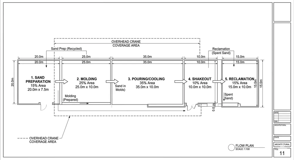
The Five Functional Zones and Their Typical Area Ratios
Every Clay Sand Processing Line layout divides into five zones. The exact dimensions depend on your production rate and equipment configuration, but the sequence and area ratios stay consistent.
Zone 1: Sand Preparation (15-20% of total floor area) This is where raw bentonite clay, silica sand, and water mix to target moisture content (typically 3.0-3.5% for green sand molding). Equipment includes a continuous mixer, moisture sensor, and buffer hopper. For an 80 molds/hour line, expect 25-35 m² for this zone. The mixer needs overhead crane access for maintenance — plan 4.5-5.0 meters vertical clearance above the mixer discharge.
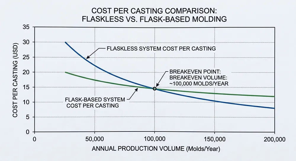
Zone 2: Molding Station (25-30% of total floor area) The molding machine sits here — either a vertical flaskless press or a horizontal flask-based system. Vertical flaskless lines need less floor area (the mold moves vertically, not horizontally) but require 6-8 meters ceiling height depending on mold size. Horizontal lines need more floor length but work in 4-5 meter ceiling spaces. For 80 molds/hour, allocate 40-55 m² depending on configuration.
We built a vertical flaskless clay sand processing line for a buyer in Thailand with only 6.2 meters ceiling height. Standard design assumes 8 meters. We shortened the mold lift stroke and added a secondary compaction stage to maintain density — it worked, but it required custom engineering. If your ceiling is below 6 meters, vertical flaskless won't fit. Plan for horizontal instead.
Zone 3: Pouring and Cooling (20-25% of total floor area) After molding, the mold moves to a pouring station (manual ladle or automated pour system) and then into a cooling conveyor. Cooling time depends on casting alloy and section thickness — gray iron castings under 10 kg typically need 8-12 minutes, ductile iron needs 15-20 minutes. The conveyor length must match your cooling time at your line speed. For 80 molds/hour (1.33 molds/minute), a 12-minute cooling cycle requires a 16-meter conveyor. That's 30-45 m² including access aisles.
Zone 4: Shakeout and Casting Separation (15-20% of total floor area) The cooled mold reaches the shakeout station, where vibration or mechanical impact separates the casting from the sand. This zone generates dust and noise — it needs exhaust ventilation (typically 8,000-12,000 m³/hr extraction rate for an 80 molds/hour line) and floor loading capacity for the vibrating equipment (4-6 tons concentrated load). Allocate 25-35 m² and confirm your floor slab can handle the dynamic load. We've seen buyers crack concrete floors because they didn't account for shakeout vibration.
Zone 5: Sand Reclamation and Return (20-25% of total floor area) Used sand from shakeout moves to a clay sand reclamation line — crushing, screening, magnetic separation, and moisture adjustment before returning to the preparation zone. Reclamation equipment is heavy (a complete system for 80 molds/hour weighs 8-12 tons) and needs crane access for screen changes and magnet maintenance. Plan 35-50 m² and 5-6 meters vertical clearance.

Step-by-Step Method to Calculate Floor Area from Production Target
Start with your target production rate in molds per hour. Then work backward through cycle time, equipment footprint, and material flow.
Step 1: Determine molding cycle time For clay sand molding, typical cycle times are:
- 40 molds/hour = 90 seconds per mold
- 80 molds/hour = 45 seconds per mold
- 120 molds/hour = 30 seconds per mold
Step 2: Calculate sand throughput Multiply molds per hour by average mold weight. For example, 80 molds/hour × 220 kg per mold = 17,600 kg/hour = 17.6 tons/hour. Your clay sand preparation line and reclamation system must handle this throughput continuously.
Step 3: Size each zone based on equipment footprint Use these approximate ranges (for 80 molds/hour as reference):
- Sand preparation: 30 m²
- Molding: 50 m²
- Pouring/cooling: 40 m²
- Shakeout: 30 m²
- Reclamation: 45 m²
- Access aisles and maintenance space: 25 m²
- Total: 220 m²
For 40 molds/hour, reduce by 30-40%. For 120 molds/hour, increase by 40-50%. The relationship isn't linear because some equipment (mixers, reclamation screens) scales in discrete steps, not continuously.
Step 4: Add expansion corridor If you plan to increase capacity later, reserve 15-20% additional floor area adjacent to the molding zone. Adding a second molding line is straightforward if you planned the space — expensive if you didn't.
Vertical Clearance, Crane Access, and Floor Loading Requirements
Floor area is only one dimension. Three more constraints determine whether your layout actually works.
Ceiling height requirements:
- Vertical flaskless molding lines: 6.0-8.0 meters (depends on mold size)
- Horizontal molding lines: 4.5-5.5 meters
- Sand preparation mixers: 4.5-5.0 meters (for overhead crane maintenance access)
- Reclamation equipment: 5.0-6.0 meters (for screen deck removal)
If your facility has 5 meters ceiling height, vertical flaskless is not an option. Plan for horizontal configuration instead.
Overhead crane coverage: Your crane must reach the mixer, molding machine hydraulic unit, and reclamation screen deck for maintenance. Typical crane capacity: 3-5 tons for equipment up to 80 molds/hour, 5-10 tons for higher capacity lines. If your facility has structural columns on a 6-meter grid, position equipment to avoid crane dead zones. We've seen buyers place a mixer in a corner where the crane couldn't reach it — they had to disassemble the mixer in place for every major repair.
Floor loading capacity:
- Sand preparation and reclamation zones: 800-1,200 kg/m² static load
- Shakeout station: 1,500-2,000 kg/m² dynamic load (vibration adds impact force)
- Molding machine: 1,000-1,500 kg/m² concentrated load
Standard industrial concrete slabs (150 mm thickness, reinforced) handle 1,000 kg/m² static load. Shakeout stations often exceed this — you may need localized floor reinforcement or a separate foundation pad. Check your facility's structural drawings before finalizing equipment placement.
Material Flow Sequence: Minimize Sand Transport Distance and Avoid Cross-Traffic
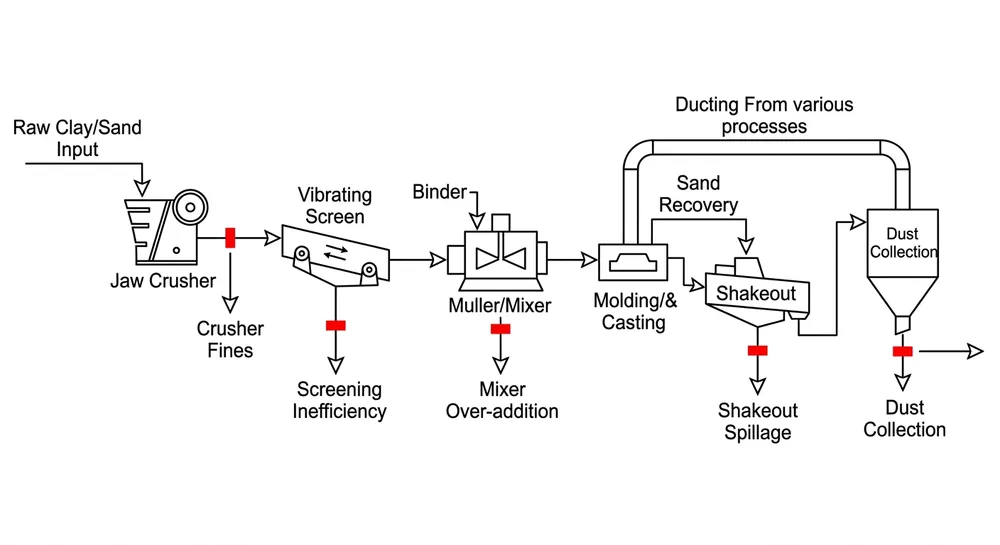
Sand moves through the line in one direction: preparation → molding → shakeout → reclamation → back to preparation. The layout should follow this sequence without backtracking or crossing paths.
Linear flow (best for new facilities): Arrange all five zones in a straight line or L-shape. Sand enters at one end, exits at the other, and returns via an overhead conveyor or underground screw conveyor. This is the cleanest layout but requires the most floor length (typically 25-35 meters for an 80 molds/hour line).
U-shaped flow (best for constrained spaces): Preparation and reclamation sit on one side, molding and shakeout on the other, with pouring/cooling connecting them. Sand flows in a U-pattern. This reduces floor length to 18-22 meters but requires more width (12-15 meters). We use this configuration when buyers have wide, short buildings.
Avoid cross-traffic between zones: If your pouring station requires forklift access for metal delivery, don't route the sand return conveyor across the forklift path. If your shakeout area needs casting removal by overhead crane, don't position the reclamation feed conveyor in the crane's swing radius. These conflicts cause production stoppages — and they're invisible on a 2D floor plan until installation day.

Common Layout Mistakes and How to Prevent Them
Mistake 1: Undersized shakeout area Buyers allocate floor space based on the shakeout machine footprint (typically 3m × 4m) but forget the casting accumulation area. At 80 molds/hour, you're producing 80 castings per hour — they need temporary storage before moving to cleaning or inspection. Add 15-20 m² for casting pallets and forklift access, or you'll have castings piling up on the floor within two hours of startup.
Mistake 2: Ignoring ventilation duct routing Shakeout and reclamation zones generate dust. Exhaust ducts (typically 400-600 mm diameter) run from each dust source to a central baghouse filter outside the building. These ducts need vertical clearance and can't cross crane paths or forklift routes. Plan duct routing during layout design, not after equipment installation. We've seen buyers cut holes in structural beams to fit ducts they didn't plan for — that's a building code violation and a safety risk.
Mistake 3: No expansion corridor Your first line runs at 60 molds/hour. Two years later, you need 120 molds/hour. If you packed equipment wall-to-wall, adding a second molding line requires relocating the entire reclamation system. Reserve 3-4 meters of open floor space adjacent to the molding zone during initial layout. It costs nothing now and saves $30,000-50,000 in reconfiguration costs later.
Mistake 4: Inaccessible maintenance points Hydraulic units, PLC cabinets, and motor drives need regular access for inspection and repair. If you position the molding machine hydraulic unit against a wall with 0.5 meters clearance, your maintenance team can't reach the valve manifold without moving the entire machine. Plan 1.5-2.0 meters clearance on at least two sides of every major equipment unit.
Mistake 5: Floor loading concentrated in one area If you place the mixer, molding machine, and reclamation system all within a 6m × 6m area, you're concentrating 15-20 tons of static load plus dynamic vibration in one spot. Spread heavy equipment across the floor to distribute load. If your facility has a weak floor area (common near building edges or above underground utilities), keep heavy equipment away from it.
How Modular Equipment Design Simplifies Layout Changes and Future Expansion
We design our clay sand processing lines to ship in 40HQ containers (12.03m length × 2.35m width × 2.69m height internal dimensions). This isn't just for freight cost — it's for layout flexibility. Equipment that fits container dimensions breaks down into modules that fit through standard doorways and reassemble without welding.
A complete 80 molds/hour line ships in 2-3 containers:
- Container 1: Molding machine frame, hydraulic unit, control cabinet
- Container 2: Sand preparation mixer, reclamation crusher, magnetic separator
- Container 3: Conveyors, shakeout station, spare parts kit
Each module bolts together on-site. If you need to reconfigure the layout later (add a second molding line, relocate the reclamation system, change from linear to U-shaped flow), you unbolt the modules and reposition them. No cutting, no welding, no permanent foundations.
We built a line for a buyer in Poland who started with 60 molds/hour in a 180 m² space. Eighteen months later, they expanded to an adjacent 220 m² building and wanted 100 molds/hour. We added a second molding machine, extended the cooling conveyor, and upgraded the reclamation screen — total reconfiguration time was nine days. The modular frame system made it possible. A welded-frame line would have required three weeks and structural modifications.
For more guidance on matching equipment capacity to your production goals, see our article on molding line capacity planning.
Facility Data Checklist: What to Prepare Before Requesting a Layout Proposal
When you contact an equipment supplier for a layout proposal, send this information upfront. It saves two weeks of back-and-forth and produces a more accurate design.
Building dimensions:
- Total floor area available (length × width in meters)
- Ceiling height (measure at lowest point, including beams and ductwork)
- Structural column spacing and locations
- Floor loading capacity (kg/m² — check your building's structural drawings)
- Door and loading dock dimensions (for equipment delivery)
Production requirements:
- Target molds per hour
- Average mold size and weight
- Casting alloy type (gray iron, ductile iron, aluminum, etc.)
- Daily operating hours and shifts per day
Existing infrastructure:
- Overhead crane capacity and coverage area (if installed)
- Electrical supply (voltage, phase, available amperage)
- Compressed air supply (pressure, flow rate)
- Water supply for sand mixing and cooling
- Exhaust ventilation capacity (if existing system must be reused)
Future expansion plans:
- Do you plan to increase capacity within 2-3 years?
- Will you add a second molding line or upgrade to higher speed?
- Are you considering automation (robotic pouring, automated shakeout)?
Our 18-engineer team at TZFoundry reviews this data and produces a preliminary layout drawing within 5-7 business days. The drawing shows equipment placement, material flow paths, crane coverage, utility connection points, and floor area allocation per zone. If your facility has constraints (low ceiling, irregular floor shape, limited crane access), we'll propose configuration options that work within those limits.

Send your facility drawing, target molds per hour, and casting alloy type to get a free preliminary layout proposal from our engineering team. Request Quote to start — we'll review your data and respond within one week with equipment recommendations and floor plan options that fit your space and production target.

Baocun Zhu is the Senior Clay Sand Process Engineer at TZFoundry in Qingdao. With over 14 years commissioning clay sand molding, reclamation, and preparation lines for export foundries, he turns floor-space constraints and throughput targets into working production systems. His...