Most foundries switching to sodium silicate sand systems underestimate the CO2 gassing station's role in final mold strength. You can run perfect binder ratios at the mixer, but if your gassing duration is off by 15 seconds or your nozzle placement misses the core's center mass, you'll see 20-30% strength loss and mold cracking during metal pour. We've commissioned 40+ resin sand lines, and sodium silicate systems fail most often at the curing stage, not the mixing stage.
Sodium silicate sand production lines use water glass (sodium silicate solution) as the binder, hardened by CO2 gas instead of chemical catalysts. The process delivers lower binder costs than furan or phenolic resin systems, zero toxic emissions during curing, and simpler environmental compliance. But it requires precise CO2 flow control, proper gassing station design, and compatible reclamation equipment to handle the silicate residue that mechanical systems struggle with.
Sodium Silicate Sand Production Line Equipment Layout
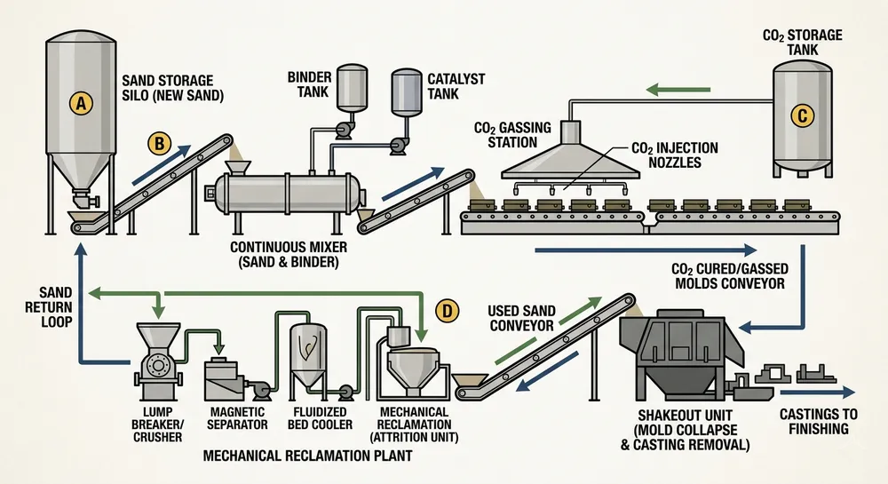
A complete sodium silicate sand production line runs from sand storage through mixing, molding, shakeout, and reclamation. The equipment sequence differs from resin sand lines because CO2 gassing happens after mold assembly, not during sand mixing.
Core equipment components:
- Continuous mixer or batch mixer: Blends reclaimed sand with 3-6% sodium silicate binder by weight. Continuous mixers handle 5-20 tons per hour for high-volume operations; batch mixers work better for foundries running multiple alloy types that need frequent sand recipe changes.
- CO2 gassing station: Delivers controlled CO2 flow through nozzles positioned in the mold or core box. Gassing duration ranges from 30 seconds to 2 minutes depending on section thickness and binder concentration. Nozzle placement matters — we position them to reach the thickest sections first because silicate curing starts at the gas contact point and moves outward.
- Conveyor and cooling zone: Moves gassed molds to the pouring area. Sodium silicate molds reach handling strength faster than furan molds (2-3 minutes vs 8-12 minutes), so conveyor speeds can run 30-40% faster if your pouring schedule supports it.
- Shakeout and sand separation: Mechanical shakeout works, but sodium silicate creates harder residue on sand grains than organic resins. Plan for higher shakeout vibration intensity or longer dwell time.
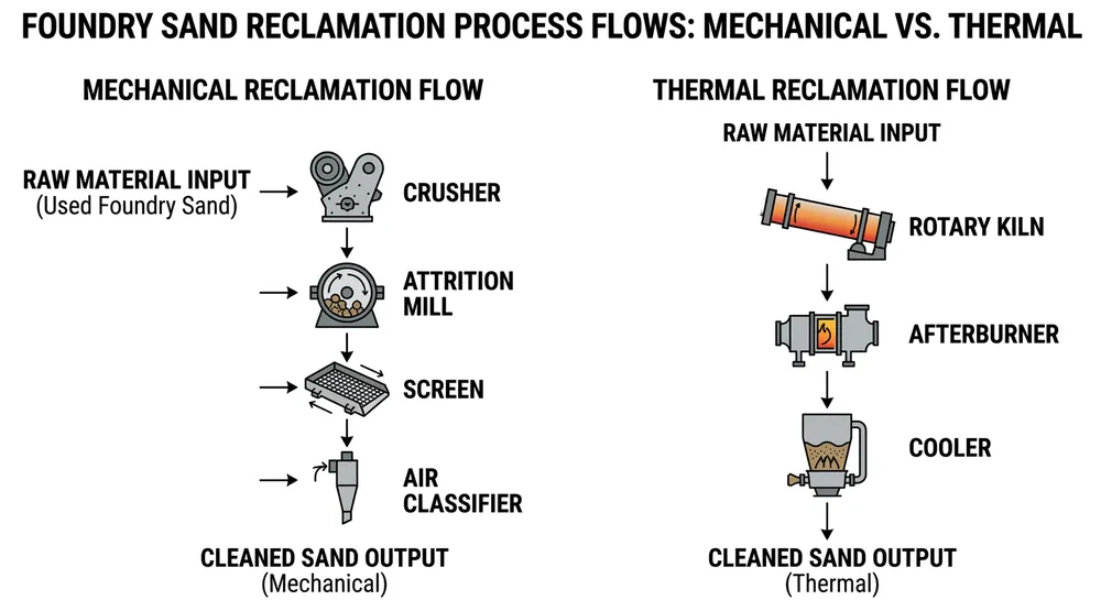
- Sand reclamation system: Mechanical reclamation (attrition mills, pneumatic impact) removes 70-85% of silicate coating. Thermal reclamation reaches 90-95% recovery but adds fuel cost. Most buyers running sodium silicate at scale use mechanical primary reclamation with periodic thermal treatment to restore sand quality.
We build complete sodium silicate lines with integrated reclamation — the mixer, gassing station, and mechanical reclamation plant ship as a coordinated system, so you're not troubleshooting compatibility issues between equipment from three different suppliers.

Binder Addition Rates and CO2 Gassing Parameters
Sodium silicate binder concentration and CO2 gassing duration control mold strength and strip time. Too little binder or too short gassing gives weak molds; too much binder or over-gassing wastes material and makes sand reclamation harder.
Typical binder addition rates:
| Sand Type | Binder Addition (% by sand weight) | Modulus (Na₂O:SiO₂ ratio) | Application |
|---|---|---|---|
| New silica sand | 4.5-6.0% | 2.4-2.8 | Cores, thin-wall molds |
| Reclaimed sand (70-80% recovery) | 5.0-6.5% | 2.6-3.0 | General molds |
| Reclaimed sand (85-95% recovery) | 3.5-5.0% | 2.4-2.6 | High-volume production |
Binder modulus (the Na₂O to SiO₂ ratio in the sodium silicate solution) affects curing speed and final strength. Lower modulus (2.4-2.6) cures faster with CO2 but gives slightly lower dry strength. Higher modulus (2.8-3.0) needs longer gassing time but delivers better high-temperature strength for steel and ductile iron casting.
CO2 gassing parameters:
- Gassing pressure: 0.15-0.25 MPa (1.5-2.5 bar). Higher pressure speeds curing but risks blowing sand out of thin sections.
- Gassing duration: 30-90 seconds for cores under 50mm thickness; 60-120 seconds for molds 100-200mm thick. We calculate gassing time as roughly 20-30 seconds per 25mm of section thickness, then verify with compression testing during commissioning.
- CO2 consumption: 0.8-1.5 kg CO2 per kg of sodium silicate binder. A foundry running 10 tons of sand per day with 5% binder addition uses 400-750 kg of CO2 daily.
The most common mistake is under-gassing thick sections. A 150mm core that gets 60 seconds of CO2 will feel hard on the surface but stay soft in the center, then crack during metal pour when the interior expands. We run test cores during commissioning and break them open to verify complete curing through the cross-section.
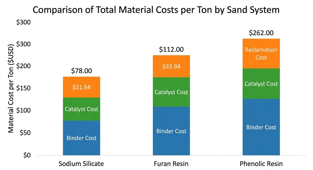
Operating Cost Comparison: Sodium Silicate vs Furan vs Phenolic
Binder cost drives the economic case for sodium silicate systems. Sodium silicate costs 40-60% less per ton than furan resin and 50-70% less than phenolic resin. But you need to account for CO2 consumption, reclamation difficulty, and mold strength requirements.
Cost breakdown per ton of molding sand:
| Cost Factor | Sodium Silicate | Furan Resin | Phenolic Resin |
|---|---|---|---|
| Binder cost (5% addition) | $15-25 | $40-60 | $50-80 |
| Catalyst/hardener cost | $8-12 (CO2) | $5-8 | $6-10 |
| Reclamation energy cost | $12-18 (mechanical + periodic thermal) | $8-12 (mechanical only) | $10-15 (mechanical + thermal) |
| Total material cost per ton | $35-55 | $53-80 | $66-105 |
Sodium silicate delivers 30-40% lower material cost than furan and 40-50% lower than phenolic. The savings scale with production volume — a foundry processing 50 tons of sand daily saves $900-1,250 per day compared to furan systems.
Environmental compliance adds another advantage. Sodium silicate produces no VOC emissions during curing (CO2 is non-toxic and non-flammable), so you avoid the exhaust treatment systems that furan and phenolic lines require. That's $15,000-30,000 in capital cost savings plus lower ongoing compliance monitoring.
The trade-off: sodium silicate molds have lower hot strength than phenolic molds, making them less suitable for large steel castings where mold erosion is a concern. For gray iron, ductile iron, and aluminum castings under 500 kg, sodium silicate works well. For steel castings over 1,000 kg or high-temperature alloys, phenolic resin gives better dimensional stability.
Sand Reclamation Compatibility and Recovery Rates
Sodium silicate creates a glassy residue on sand grains after casting that's harder to remove than organic resin films. Mechanical reclamation alone typically recovers 70-85% of sand quality (measured by AFS clay content and loss on ignition). Thermal reclamation reaches 90-95% recovery but adds fuel cost.
Mechanical reclamation process for sodium silicate sand:
- Primary crushing: Breaks up large silicate lumps and separates metal from sand. Jaw crushers or impact mills work better than rotary screens because silicate bonds are brittle under impact.
- Attrition scrubbing: High-speed rotating paddles rub sand grains against each other to remove silicate coating. Attrition time runs 3-5 minutes for sodium silicate vs 2-3 minutes for furan sand. Longer scrubbing increases sand grain breakage, so you'll see gradual AFS grain fineness number increase over time.
- Pneumatic separation: Air classifiers remove dust and fine particles. Sodium silicate dust is hygroscopic (absorbs moisture from air), so dust collection systems need sealed hoppers and regular emptying to prevent caking.
- Magnetic separation: Removes tramp metal. Standard for all sand reclamation, not specific to sodium silicate.
We run sand samples through our in-house reclamation testing lab before shipping equipment. If you're buying a mechanical reclamation line rated for 85% recovery on sodium silicate sand, we'll show you the test data from your specific unit running your sand type and binder concentration. That's not a spec sheet — it's measured performance from the equipment you're receiving.
When to add thermal reclamation:
If your foundry runs continuous production and you're seeing AFS clay content creep above 1.5% or loss on ignition above 3.0% after mechanical reclamation, add a thermal reclamation unit. Thermal systems heat sand to 600-700°C to burn off residual silicate, restoring sand to near-new quality. Fuel cost runs $8-15 per ton of sand depending on local natural gas or LPG pricing.
Most buyers use a hybrid approach: mechanical reclamation for daily production, thermal reclamation for 10-20% of sand flow to maintain overall quality. This keeps reclamation cost reasonable while preventing gradual sand degradation.
Commissioning and First-Production Troubleshooting
Sodium silicate lines fail most often during commissioning because buyers underestimate how sensitive CO2 gassing is to nozzle placement, flow rate, and ambient humidity. We've commissioned systems in 14 countries via remote video support, and these are the issues that show up in the first week.
Common commissioning problems:
- Incomplete curing in thick sections: Gassing duration calculated for average section thickness doesn't account for the thickest areas. Solution: add 20-30% to calculated gassing time for complex geometries, or add secondary gassing nozzles targeting thick sections.
- Surface hardening with soft interior: CO2 pressure too high or gassing time too short. The surface cures and seals, blocking CO2 penetration to the core. Solution: reduce gassing pressure to 0.15-0.18 MPa and extend duration by 30-50%.
- Mold cracking during handling: Over-gassing or binder concentration too high. Sodium silicate becomes brittle when over-cured. Solution: reduce gassing time by 15-20% or drop binder addition by 0.5%.
- Poor strip time (molds stick to pattern): Binder modulus too high or gassing incomplete. Solution: switch to lower modulus sodium silicate (2.4-2.6 range) or verify CO2 flow reaches all mold surfaces.
We program commissioning sequences into the PLC before shipment, so your first production run follows tested parameters. The HMI touchscreen shows real-time CO2 flow rate, gassing duration countdown, and binder addition percentage. If something's wrong, your maintenance team can pull error logs remotely and we'll adjust parameters without flying an engineer to the site.
Sodium Silicate Sand Line Selection Guide
Choose sodium silicate sand systems when binder cost and environmental compliance matter more than maximum hot strength. The decision depends on your casting type, production volume, and local environmental regulations.
Sodium silicate works well for:
- Gray iron and ductile iron castings under 500 kg
- Aluminum and copper alloy castings (all sizes)
- High-volume production where binder cost significantly impacts margin
- Regions with strict VOC emission limits
- Foundries without existing exhaust treatment infrastructure
Consider furan or phenolic resin instead for:
- Steel castings over 1,000 kg where mold erosion is a concern
- High-temperature alloys (stainless steel, high-nickel alloys)
- Complex geometries requiring maximum dimensional accuracy
- Low-volume job shops where binder cost is less critical than setup flexibility
If you're running mixed production (both iron and steel castings), some foundries operate parallel lines — sodium silicate for iron work, phenolic for steel. That requires duplicate equipment investment but maximizes cost efficiency across your product mix.
TZFoundry builds complete sodium silicate sand lines from mixer through reclamation, with CO2 gassing stations designed for your specific mold sizes and production rate. Our systems ship in modular sections that fit 40HQ containers, with remote commissioning support and first-year spare parts kits included. Send us your casting type, daily sand throughput, and available floor space — we'll spec the exact configuration and provide factory pricing with commissioning data from similar installations.
For more information on resin sand production line options, see our resin sand production line category page. If you're comparing binder systems or need help calculating total operating cost for your specific production volume, contact our engineering team with your casting specifications.

Liu Haoran is the Resin Sand Production Line Technical Manager at TZFoundry. Over 11 years of hands-on work with furan, phenolic, and coated sand systems, he has commissioned 40+ resin sand lines for export buyers and developed binder dosing protocols...