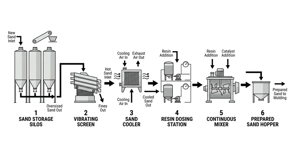
Uneven resin coating across a sand batch shows up as hot spots on the casting surface, premature mold breakdown during pouring, or sand burn-on that adds 20-30% to your shakeout labor cost. The problem gets worse when you're running mixed grain sizes or switching between AFS 40 and AFS 70 sand without adjusting your coating plant parameters. Most foundries discover the coating variance after the casting fails — by then, you've already wasted the resin, the metal, and the production time.
The root cause isn't the sand itself. It's the mismatch between your coating plant's mixing speed, resin feed rate, and heating temperature versus the specific surface area of the grain size you're processing. Finer sand (higher AFS number) has more surface area per kilogram, so it needs different resin distribution mechanics than coarse sand. If your mixer RPM and resin dosing stay fixed across all grain sizes, you'll get thick coating on some particles and bare spots on others.
Why Coating Uniformity Breaks Down Across Grain Sizes
Resin coating uniformity depends on three mechanical factors: how fast the sand particles tumble through the resin spray zone, how much resin contacts each particle surface, and how evenly the heat cures the resin film before discharge. When you switch from AFS 50 (coarse) to AFS 65 (fine) without adjusting parameters, the finer particles move differently inside the mixer drum.
Finer sand has 40-60% more surface area per unit weight compared to coarse sand. That means the same resin percentage by weight produces a thinner coating film on fine sand. If you're targeting 1.5% resin addition, AFS 50 sand gets a film thickness around 8-12 microns, while AFS 65 sand only gets 5-8 microns with the same resin mass. The thinner film on fine sand cures faster under heat, but it also breaks down faster under mechanical stress during sand handling and mold compaction.
Mixer speed compounds the problem. At 28-32 RPM (typical for AFS 50 sand), coarse particles tumble in a cascading pattern that exposes all surfaces to the resin spray nozzles. Fine sand at the same RPM tends to form a rolling bed instead of cascading — the particles on the inside of the bed never pass through the spray zone, so they stay uncoated or under-coated. We've measured coating weight variance as high as 0.8% within a single batch when mixer speed isn't adjusted for grain size.
Temperature control matters more than most operators realize. Coarse sand retains less heat per particle because of lower surface-to-volume ratio, so it needs higher mixer jacket temperature (140-160°C) to cure the resin film. Fine sand heats up faster and holds temperature longer, so the same 160°C setting can over-cure the resin, making the coated sand brittle and prone to dust generation during pneumatic conveying.
Step-by-Step Parameter Adjustment for Different Grain Sizes
Start by confirming your sand's actual AFS grain fineness number through sieve analysis. Don't rely on supplier labels — we've seen "AFS 55" sand test out at AFS 62 after transport and handling. The AFS number determines your baseline coating parameters.
For AFS 40-50 (coarse sand):
- Mixer speed: 28-32 RPM
- Resin feed rate: 1.2-1.8% by sand weight (depends on resin type — phenolic runs lower, furan runs higher)
- Mixer jacket temperature: 140-160°C
- Mixing time: 90-120 seconds
- Discharge temperature target: 135-145°C
For AFS 50-60 (medium sand):
- Mixer speed: 24-28 RPM
- Resin feed rate: 1.5-2.0% by sand weight
- Mixer jacket temperature: 130-150°C
- Mixing time: 80-100 seconds
- Discharge temperature target: 130-140°C
For AFS 60-70 (fine sand):
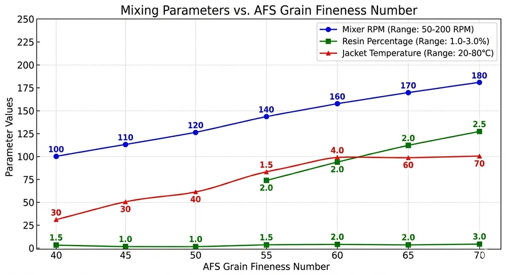
- Mixer speed: 20-24 RPM
- Resin feed rate: 1.8-2.2% by sand weight
- Mixer jacket temperature: 120-140°C
- Mixing time: 70-90 seconds
- Discharge temperature target: 125-135°C
The resin feed rate increases with finer sand because you're coating more surface area. The mixer speed decreases to prevent bed rolling and ensure cascading flow. The temperature drops to avoid over-curing the thinner resin film on fine particles.
(Note: these ranges assume continuous coating plants with horizontal drum mixers. Batch-type mixers need 10-15% longer mixing time to achieve the same coating distribution.)
Adjust resin feed rate first, then mixer speed, then temperature. If you change all three at once and the coating still comes out uneven, you won't know which parameter caused the problem. Make one adjustment, run a test batch, measure coating weight variance, then adjust the next parameter.

Validation Checks for Coating Uniformity
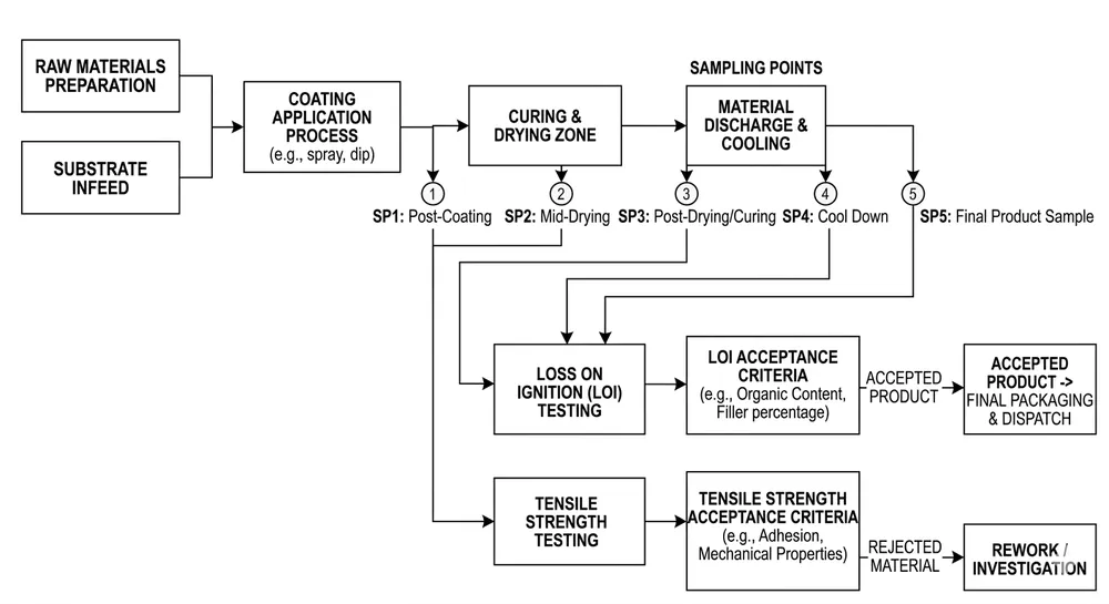
Measure coating weight variance across the batch, not just average coating percentage. Pull five samples from different discharge points (start, 25%, 50%, 75%, end of batch) and run loss-on-ignition testing to determine resin content. Acceptable variance is ±0.15% for most casting applications. If you're seeing ±0.3% or wider, your parameters need adjustment.
Visual inspection catches obvious problems but misses the failures that show up during casting. Look for dust generation when you pour coated sand from one container to another — excessive dust means over-curing or resin film breakdown. Check for sand clumping or agglomeration, which indicates under-mixing or resin pooling instead of even distribution.
Tensile strength testing on sample cores gives you the downstream performance data. Mix coated sand with catalyst, blow a standard test core (50mm diameter × 50mm height), cure for the specified time, then test tensile strength. For phenolic resin systems, you should see 1.8-2.5 MPa at 24-hour cure. If strength varies more than 15% between cores made from the same coated sand batch, coating uniformity is the likely cause.
We run coating uniformity validation in our sand reclamation testing lab before shipping coating plants. The test protocol measures coating weight variance, particle size distribution after coating, and tensile strength consistency across a 500 kg batch. If the equipment can't hold ±0.15% coating variance on AFS 55 sand at 1.5% resin addition, it doesn't leave the factory. (We learned this after a 2018 installation in Poland where coating variance caused a 12% reject rate on ductile iron castings — the buyer's QC team traced it back to inconsistent resin distribution, and we had to retrofit the mixer with variable-speed drive and upgraded spray nozzles.)
Upstream Equipment Factors That Control Coating Quality
Coating uniformity problems often start with the equipment design, not operator error. Mixer drum geometry determines whether sand cascades or rolls. A drum with 12-16 internal flights (angled blades welded to the drum interior) creates the cascading action needed for even resin distribution. Drums with fewer than 10 flights or worn flight edges let the sand bed roll instead of cascade, especially with fine sand.
Resin spray nozzle placement and atomization quality matter more than most foundries realize. Nozzles mounted too close to the drum wall create resin pooling on the outer sand layer. Nozzles with worn orifices produce droplets instead of fine mist, leading to resin clumping. We position spray nozzles at 30-40% of drum radius from the center axis and replace nozzles every 2,000 operating hours to maintain atomization quality.
PLC-controlled resin dosing systems eliminate the manual flow-rate adjustment errors that cause batch-to-batch coating variance. A gear pump with closed-loop flow feedback holds resin feed rate within ±2% across the entire batch, even when resin viscosity changes with ambient temperature. Manual valve-controlled systems can drift ±8-12% during a production shift, and operators don't notice until the coated sand fails tensile testing.
Variable-frequency drive (VFD) control on the mixer motor lets you adjust RPM in 1-RPM increments and save parameter sets for different grain sizes. Fixed-speed motors force you to run the same RPM for all sand types, which guarantees coating problems when you switch between coarse and fine sand. Our resin sand production line equipment uses Siemens or Mitsubishi VFDs with touchscreen parameter storage — you can recall the AFS 55 parameter set with two button presses instead of manually adjusting three separate controls.
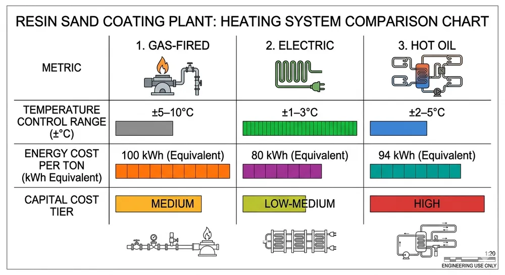
Temperature control depends on jacket heating design and insulation quality. Steam-jacketed mixers give faster heat transfer but require boiler infrastructure. Electric heating elements are simpler but slower to respond when you adjust setpoint temperature. Either system needs 50mm minimum insulation thickness on the drum exterior to prevent heat loss and maintain stable coating temperature. We've seen coating plants lose 15-20°C between mixer jacket and discharge point because of inadequate insulation — that temperature drop under-cures the resin film and causes coating breakdown during sand handling.
When Coating Problems Start Before the Coating Plant
Sand moisture content above 0.3% causes resin to foam instead of forming a smooth film. The moisture flashes to steam when it contacts the hot mixer drum, creating bubbles in the resin coating. Those bubbles collapse during cooling, leaving pinholes and thin spots in the coating. If you're getting coating uniformity problems even after adjusting all the mixer parameters, check incoming sand moisture with a moisture analyzer. Most suppliers ship sand at 0.1-0.2% moisture, but transport in humid climates or outdoor storage can push it above 0.5%.
Sand temperature before coating affects how fast the resin cures. Cold sand (below 20°C) needs higher mixer jacket temperature to reach target discharge temperature, but the extended heating time can over-cure the resin on particles that entered the mixer first. Pre-heating sand to 40-50°C with a fluidized bed dryer or rotary dryer gives you more consistent coating results, especially in winter production.
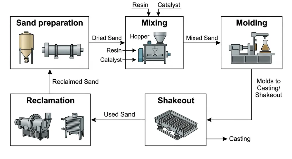
Residual clay content in reclaimed sand interferes with resin adhesion. Clay particles coat the sand grain surface and prevent the resin from bonding directly to the silica. If you're running mechanical reclamation without attrition scrubbing, clay content can reach 0.8-1.2% in the reclaimed sand. That's enough to cause 20-30% reduction in coated sand tensile strength and visible coating non-uniformity. Thermal reclamation burns off the clay, but mechanical reclamation needs an attrition scrubber stage to remove clay films before the sand goes to the coating plant.
Grain size distribution drift is common when you're blending sand from multiple suppliers or mixing new sand with reclaimed sand. If your target is AFS 55 but the actual distribution spans AFS 50-62, you'll never get uniform coating because different grain sizes need different parameters. Run sieve analysis weekly on incoming sand and adjust your blend ratios to hold AFS number within ±3 points. Tighter control costs you 10 minutes of lab time per week but saves you from coating variance problems that waste resin and generate scrap castings.
Practical Recommendations for Foundries Running Multiple Grain Sizes
If you're switching between coarse and fine sand more than twice per shift, invest in PLC parameter storage and automated changeover. Manual parameter adjustment takes 15-20 minutes per changeover and introduces operator error. Automated systems recall the correct mixer speed, resin feed rate, and temperature settings in under 2 minutes, and the parameters stay consistent across all shifts.
For foundries running AFS 50-60 sand exclusively, a fixed-speed coating plant with manual resin dosing can work if you're disciplined about process control. But if your casting mix includes both aluminum (typically AFS 55-65 sand) and iron (typically AFS 45-55 sand), you need variable-speed mixing and automated resin dosing to maintain coating uniformity across both sand types.
Start with coating weight variance measurement, not just average resin percentage. Most foundries track "we're adding 1.5% resin" but don't measure whether that 1.5% is distributed evenly. Five-point sampling and LOI testing takes 90 minutes but tells you whether your coating plant is actually working or just consuming resin. If variance is above ±0.2%, adjust parameters before you waste another batch.
When you're evaluating coating plant equipment, ask for coating weight variance data from the manufacturer's test runs, not just rated capacity and resin percentage range. A coating plant rated for 5 tons/hour at 1.5% resin addition is meaningless if it can't hold ±0.15% variance across the batch. We provide test reports from our sand reclamation lab showing actual coating variance measured on your specified grain size and resin system before the equipment ships.
If you're experiencing coating uniformity problems with existing equipment, check mixer drum flight condition first, then resin nozzle atomization quality, then temperature control stability. Those three factors cause 80% of coating variance issues. Replacing worn flights and nozzles costs less than 5% of a new coating plant but can cut coating variance in half.
For technical guidance on coating plant parameter optimization for your specific sand type and resin system, contact our resin sand production line engineering team. We'll review your current parameters, grain size distribution, and coating variance data, then recommend the adjustments or equipment upgrades that will get you to ±0.15% coating uniformity. Send your sand specifications and current coating plant details to sales@tzfoundry.com or reach us on WhatsApp at +86 13335029477.

Liu Haoran is the Resin Sand Production Line Technical Manager at TZFoundry. Over 11 years of hands-on work with furan, phenolic, and coated sand systems, he has commissioned 40+ resin sand lines for export buyers and developed binder dosing protocols...