Most foundries discover their ceiling is too low after they've already requested a quote. You measure 7 meters, the supplier's standard design needs 8, and now you're either modifying the building or walking away from the equipment. We've had this conversation 40+ times in the last three years, so let's address the space question before you waste time on a configuration that won't fit.
A Vertical Flaskless Clay Sand Processing Line occupies vertical space for the molding press tower, horizontal space for sand handling and conveyor systems, and below-grade space for sand return pits. The total facility footprint depends on your hourly output target, but the ceiling height constraint hits first — if your building can't clear the press height plus crane hook travel, the rest of the layout doesn't matter.
Ceiling Height: The First Constraint
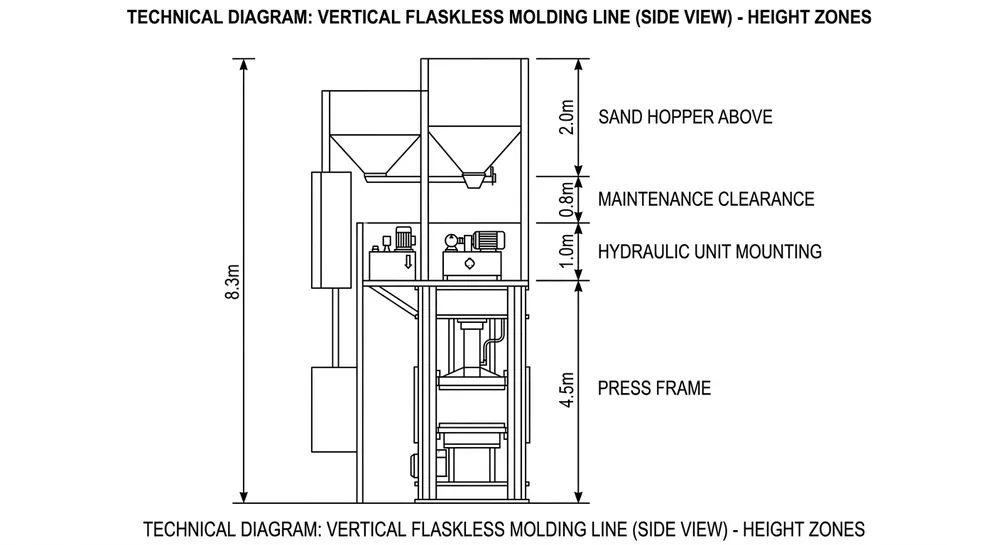
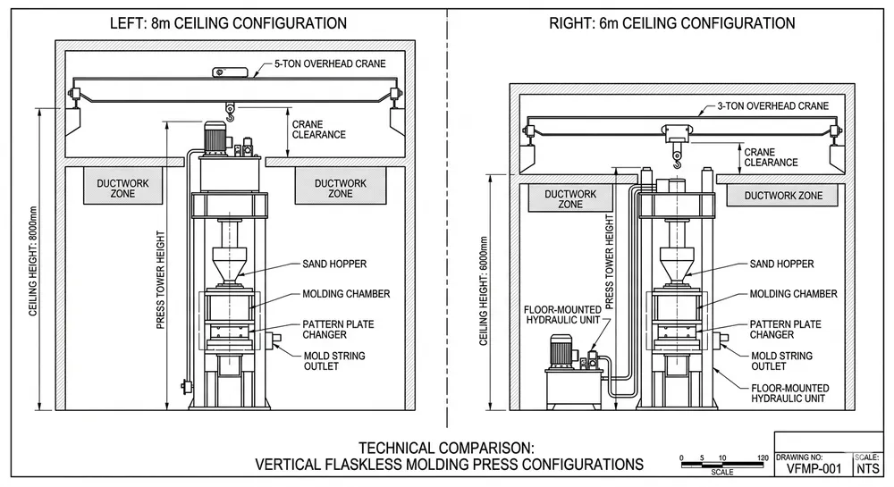
Standard vertical flaskless molding lines assume 8 meters of clear ceiling height. That's measured from finished floor to the bottom of any overhead obstruction — crane rails, ductwork, structural beams, lighting fixtures. The 8-meter figure breaks down into three zones: 4.2-4.8 meters for the molding press tower itself (varies by mold size), 2.5-3.0 meters for overhead crane hook travel and rigging clearance, and 0.5-1.0 meters for dust extraction ductwork and electrical cable trays.
We've adapted lines to run in 6-meter buildings, but it requires design changes. The molding press gets a lower profile by relocating the hydraulic power unit from the top of the tower to floor level beside the machine. Overhead crane capacity drops from 5 tons to 3 tons, and hook height reduces to 2.2 meters — enough to lift a mold flask for maintenance but not enough for full pattern plate changes without a mobile crane. Dust extraction switches from overhead hoods to side-mounted suction points. These modifications add 8-12 weeks to delivery time because we're building outside our standard production sequence.
If your ceiling sits below 6 meters, vertical flaskless becomes impractical. At that point, a Horizontal Flaskless Clay Sand Processing Line makes more sense — those systems need 3.5-4.0 meters of ceiling clearance and spread the equipment across a longer floor run instead of stacking it vertically.

Floor Space by Capacity Tier
Floor area scales with hourly output because higher production rates need larger sand storage hoppers, longer cooling conveyors, and more shakeout stations. Here's what we typically see:
| Capacity (molds/hr) | Molding Press Footprint | Sand System & Conveyor | Shakeout & Cooling | Total Floor Area | Typical Layout |
|---|---|---|---|---|---|
| 60-80 | 3.5m × 4.0m | 8m × 3m | 6m × 4m | 120-150 m² | Single line, compact |
| 120-150 | 4.0m × 5.0m | 12m × 4m | 10m × 5m | 200-250 m² | L-shaped or linear |
| 200-250 | 4.5m × 6.0m | 18m × 5m | 14m × 6m | 350-400 m² | U-shaped with return loop |
These numbers assume a complete processing line — molding press, sand mixer, sand hopper, mold conveyor, shakeout station, and sand reclamation return. If you're only installing the molding press and feeding it from an existing sand system, cut the floor area by 40%.
The 120-150 molds/hr tier is the most common export configuration. It fits in a 15m × 18m bay, which matches the column spacing in most industrial buildings constructed after 1990. The 200+ molds/hr systems need custom facility planning because the conveyor run exceeds standard bay widths — you're either knocking out columns or routing the conveyor through an adjacent bay.
Container shipping dimensions constrain the maximum size of any single sub-assembly. Our equipment ships in 40HQ containers (12.03m length × 2.35m width × 2.69m height internal), so the molding press frame can't exceed 11.8 meters in any knocked-down dimension. This is why vertical flaskless presses above 250 molds/hr start requiring field-welded frame extensions — the structural tower gets too tall to ship intact.
Pit Depth and Foundation Requirements
Vertical flaskless lines need a below-grade sand return pit positioned directly under the shakeout station. Castings drop onto a vibrating grid, sand falls through into the pit, and a screw conveyor or bucket elevator lifts the sand back to the reclamation system. Pit depth runs 1.5-2.5 meters depending on your sand return method.
Screw conveyor systems (the most common choice) need 1.5-1.8 meters of pit depth. The screw sits at the bottom of a sloped hopper, and sand flows by gravity to the intake. Bucket elevator systems need 2.2-2.5 meters because the buckets require vertical travel distance to build momentum before they hit the discharge chute. We prefer screw conveyors for export installations because they have fewer moving parts and don't jam as easily when a casting fragment gets mixed into the sand.
If your facility sits on a concrete slab with no excavation access, you can build an above-grade sand return using a raised shakeout platform. The mold conveyor ramps up 2 meters, castings drop onto the shakeout grid at elevated height, and sand falls into a floor-level hopper. This adds 15-20% to your installation cost because you're building structural platforms and access stairs, but it eliminates the pit excavation.
Foundation loading concentrates at the molding press. A 120 molds/hr press generates 150-180 tons of compaction force, and that load transfers through four mounting points into the floor slab. We specify 300mm thick reinforced concrete with 250 kg/cm² compressive strength under the press footprint. Most industrial floors built after 2000 meet this spec, but older facilities sometimes have 200mm slabs that need reinforcement pads poured before installation.
Vibration isolation matters if your facility has precision machining or quality control labs nearby. The molding press cycles every 25-45 seconds (depending on mold size), and each cycle generates a sharp impact load when the squeeze plate compresses the sand. We mount the press on 50mm neoprene isolation pads to absorb 70-80% of the vibration energy, but you'll still feel a noticeable thump within 10 meters of the machine. (One buyer installed a vertical flaskless line 8 meters from their CMM inspection room and had to relocate the CMM after commissioning — the vibration was throwing off measurement repeatability.)

Utility Clearance and Access Zones
Overhead crane coverage needs to reach the molding press for pattern plate changes and the sand mixer for maintenance access. A 5-ton crane with 2.5-3.0 meters of hook travel below the rail handles both tasks. Crane rail height sits 1.5-2.0 meters below your ceiling — if you have 8 meters of clear height, the rail mounts at 6.0-6.5 meters, leaving 2.5-3.0 meters of hook travel to reach equipment at floor level.
Electrical panels mount on the wall adjacent to the molding press, typically 1.5m × 2.0m footprint for a 120 molds/hr system. You need 1.2 meters of clear access space in front of the panel for maintenance work — this is an electrical code requirement in most countries, not a suggestion. We've seen buyers try to squeeze panels into 0.8-meter aisles to save floor space, and it creates problems during commissioning when the electrician can't physically reach the terminal blocks.
Compressed air supply runs at 6-8 bar for pneumatic valves and cylinder actuators. A 120 molds/hr line consumes 1.2-1.5 m³/min of compressed air, which requires a 15-20 HP compressor if you're dedicating one to the molding line. Most foundries run a central compressed air system, so you're just routing a 50mm supply line from your existing header to the molding press. Make sure your air system includes a dryer — moisture in the air lines causes valve sticking and cylinder seal degradation.
Dust extraction pulls 3,000-5,000 m³/hr of air from the sand mixer, molding press, and shakeout station. Ductwork runs 300-400mm diameter, and it needs a clear routing path from each pickup point to your central dust collector or baghouse. We've had installations where the buyer didn't account for duct routing during layout planning, and we ended up running ducts across the ceiling at angles that blocked crane travel. Plan the duct path before you finalize equipment placement.
Power supply for a 120 molds/hr line runs 80-120 kW total load (molding press hydraulic pump, sand mixer motor, conveyor drives, dust extraction fan). That's a 150-200 kVA transformer if you're feeding the line from a dedicated circuit. Voltage options are 380V/400V/415V three-phase 50Hz or 440V/480V three-phase 60Hz — we configure the motors and control system to match your local power standard during manufacturing.
Facility Readiness Checklist
Before you request a quote, measure and document these dimensions. It saves 2-3 rounds of back-and-forth clarification and gets you an accurate layout drawing faster.
Building dimensions:
- Clear ceiling height from finished floor to lowest obstruction (measure at multiple points — some buildings have sloped roofs or dropped ceiling sections)
- Available floor area in meters (length × width)
- Column spacing and locations if the building has structural columns
- Door and loading dock dimensions for equipment receiving
Foundation and pit:
- Floor slab thickness and concrete strength if known (check construction drawings or ask your facility manager)
- Ability to excavate a 1.5-2.5 meter pit, or need for above-grade sand return
- Distance to nearest precision equipment or vibration-sensitive operations
Utilities:
- Overhead crane capacity and hook height, or need for crane installation
- Electrical service capacity and voltage (check your main panel rating)
- Compressed air system pressure and available flow rate
- Dust collection system capacity or need for dedicated dust collector
Access and clearance:
- Rigging access for equipment installation (can a forklift or mobile crane reach the installation area?)
- Aisle width around equipment for maintenance access
- Routing path for ductwork, cable trays, and compressed air lines
Take photos of the installation area from multiple angles. Include shots of the ceiling structure, floor condition, existing equipment layout, and utility connection points. We use these photos during layout design to spot potential interference issues that don't show up in dimension lists.
Real Project: 6-Meter Ceiling Adaptation
We modified a 120 molds/hr vertical flaskless line for a Middle Eastern buyer whose existing foundry building had 6.2 meters of clear ceiling height. The standard design needed 8 meters, so we relocated the hydraulic power unit from the top of the molding press tower to a floor-mounted position 2 meters away from the press. This dropped the press tower height from 4.8 meters to 3.6 meters.
Overhead crane capacity reduced from 5 tons to 3 tons because the lower hook height couldn't safely lift the heavier pattern plates. The buyer accepted this trade-off because they were running smaller molds (500mm × 400mm flask size) that didn't need the full 5-ton capacity anyway. Dust extraction switched from overhead hoods to side-mounted suction points positioned at sand mixer discharge and shakeout grid level.
The modification added 10 weeks to the delivery schedule because we built the press outside our standard production sequence. Engineering time added $8,000 to the project cost for custom layout drawings and hydraulic line rerouting. The buyer saved $45,000 by avoiding building modifications, so the economics worked in their favor.
That project taught us where the ceiling height flexibility ends. Below 6 meters, you start compromising functional access — maintenance crews can't reach the top of the press tower without scaffolding, and pattern plate changes require a mobile crane instead of the overhead crane. At that point, switching to a horizontal configuration makes more sense than forcing a vertical design into an undersized building.
Vertical vs. Horizontal: Space Trade-Offs
Vertical flaskless lines stack equipment vertically to minimize floor area, but they need 6-8 meters of ceiling clearance. Horizontal flaskless lines spread equipment across a longer floor run and only need 3.5-4.0 meters of ceiling height. Here's how the space requirements compare for a 120 molds/hr system:
Vertical configuration:
- Floor area: 200-250 m²
- Ceiling height: 8m (standard) or 6m (modified)
- Layout: Compact, fits in a square bay
- Best for: Facilities with high ceilings and limited floor space
Horizontal configuration:
- Floor area: 300-350 m²
- Ceiling height: 3.5-4.0m
- Layout: Linear, requires a long narrow bay
- Best for: Facilities with low ceilings and available floor length
Most export buyers choose vertical configurations because overseas foundry buildings tend to have 8-10 meter ceilings (industrial buildings in North America, Europe, and the Middle East typically follow this standard). Horizontal lines show up more often in retrofit projects where the buyer is adding capacity to an older building with lower ceilings.
The Clay Sand Processing Line category page covers both configurations in detail if you're still deciding which layout fits your facility better.
What to Send When You Request a Quote
Submit your facility dimensions along with your production requirements, and we'll provide a layout drawing that shows exact equipment placement, utility connection points, and clearance zones. The drawing confirms whether your building can accommodate the line or identifies what modifications you'd need.
Minimum information for an accurate layout:
- Target mold size (flask dimensions in mm)
- Hourly production rate (molds per hour)
- Available floor area (length × width in meters)
- Clear ceiling height (measured to lowest obstruction)
- Pit excavation capability (yes/no, and maximum depth if yes)
- Overhead crane availability (capacity and hook height, or "none")
Helpful additional information:
- Photos of the installation area
- Existing equipment layout if you're adding to a current production line
- Electrical service voltage and available capacity
- Compressed air system pressure and flow rate
- Any space constraints (columns, existing equipment, access doors)
Our engineering team reviews the facility data and produces a layout drawing within 5-7 business days. The drawing shows equipment footprints, aisle clearances, utility routing, and crane coverage zones. If your building needs modifications, we'll note what changes are required and provide cost estimates for both the standard configuration and any custom adaptations.
You can submit facility dimensions and production requirements through our Request Quote page — include photos if you have them, and mention if you're working with a low-ceiling building so we can evaluate modification options upfront.

Baocun Zhu is the Senior Clay Sand Process Engineer at TZFoundry in Qingdao. With over 14 years commissioning clay sand molding, reclamation, and preparation lines for export foundries, he turns floor-space constraints and throughput targets into working production systems. His...