Compaction pressure problems cost foundries 8-15% of their production in scrap and rework. A batch of iron castings rejected for surface penetration defects, a run of aluminum parts with blowholes that only show up after machining, or molds that crush during metal pouring — all of these trace back to the same root cause: compaction pressure that doesn't match your sand properties and casting requirements.
We've commissioned over 60 Clay Sand Molding Lines across four continents, and the most common startup problem isn't mechanical failure or control system bugs. It's operators running default pressure settings that were never calibrated for their specific sand mix, mold size, or alloy type. The line runs fine during dry cycles, then starts producing defective castings the moment metal hits the molds.
This guide walks through the diagnostic process we use during commissioning to identify compaction-related defects, separate them from sand composition problems, and adjust PLC parameters to bring defect rates below 2%.
Why Compaction Pressure Determines Mold Quality
Clay sand molds need enough compaction to resist metal pressure during pouring, but not so much that the sand loses permeability or creates internal stress concentrations. The relationship is mechanical: compaction pressure controls mold hardness, and mold hardness determines which defects you'll see.
Under-compacted molds (hardness below 70 on the standard hardness scale) allow metal penetration into the sand surface, create rough casting finishes, and can collapse under metal pressure in thin-wall sections. The mold surface doesn't have enough density to resist molten metal flow, so you get sand inclusions and penetration defects that require grinding or shot blasting to remove.
Over-compacted molds (hardness above 95) trap gas during metal pouring because the sand loses permeability. Gas can't escape through the mold walls, so it forms blowholes in the casting. Over-compaction also creates internal stress in the mold that can cause cracking during pattern withdrawal or metal pouring. We see this most often on large molds where operators increase pressure trying to improve surface finish, then wonder why blowhole rates jump from 3% to 12%.
The target range for most ferrous castings sits between 80-90 hardness. Aluminum and other non-ferrous alloys typically run 75-85 because lower pouring temperatures reduce metal pressure on the mold walls. But these are starting points, not universal rules — your optimal pressure depends on sand compactability, moisture content, mold geometry, and casting alloy.
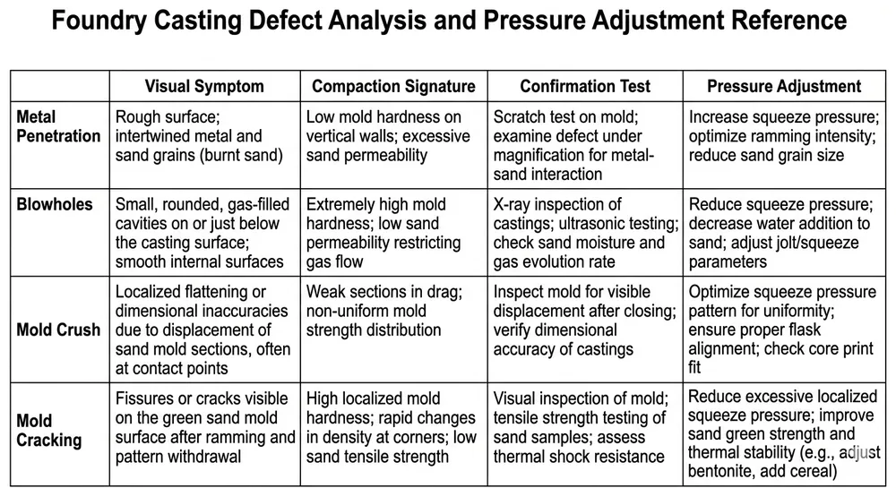
The Four Compaction-Related Defects and Their Pressure Signatures
Before adjusting anything, you need to confirm that compaction pressure is actually causing your defects. Sand composition problems, pattern alignment issues, and pouring technique errors can produce similar symptoms. Here's how to separate compaction-related defects from other root causes.
Defect 1: Metal Penetration and Rough Surface Finish
Visual symptom: Sand grains embedded in the casting surface, rough texture that requires excessive grinding, or a "burned-on" sand layer that's difficult to remove during shakeout.
Compaction signature: Mold hardness below 75, typically concentrated on cope surfaces or thin-wall sections where squeeze pressure didn't reach. If you measure hardness across the mold face and find 15-20 point variations, your pressure distribution is uneven.
Confirmation test: Pull a mold before pouring and check hardness at five points: center, four corners. If the center reads 85 but corners read 65, your squeeze plate isn't applying uniform pressure. This is a mechanical problem (worn guide pins, misaligned squeeze head), not a pressure setting issue.
Pressure adjustment: Increase compaction pressure in 0.2-0.3 bar increments. On PLC-controlled lines, this adjusts via the HMI under "Molding Parameters > Squeeze Pressure." Test one mold, measure hardness, pour a casting, and inspect surface finish before committing to a full production run.
Defect 2: Blowholes and Gas Porosity
Visual symptom: Round or irregular voids near the casting surface, often concentrated in heavy sections or at the top of vertical castings. Blowholes may not be visible until after machining removes 2-3mm of surface material.
Compaction signature: Mold hardness above 92, combined with low permeability readings (below 120 on AFS permeability test). The sand is so dense that gas generated during metal pouring can't escape through the mold walls.
Confirmation test: Run an AFS permeability test on sand pulled from a freshly compacted mold. If permeability drops below 100, you've over-compacted the sand and destroyed its ability to vent gas. Compare this to permeability of the prepared sand before molding — if prepared sand reads 180 and molded sand reads 95, you're crushing the sand structure.
Pressure adjustment: Reduce compaction pressure in 0.2 bar increments. Monitor both mold hardness and permeability. The goal is to find the lowest pressure that still gives you adequate surface finish — typically this lands you at 82-88 hardness with permeability above 130.
Defect 3: Mold Crush and Swell
Visual symptom: Castings with dimensions larger than pattern dimensions, particularly in vertical walls or deep pockets. Severe cases show mold wall collapse during pouring, creating flash or completely misshapen castings.
Compaction signature: Mold hardness below 70 in load-bearing sections, or uneven hardness distribution where thin mold sections read 20-30 points lower than thick sections. This happens when squeeze pressure can't reach into deep pockets or around complex core assemblies.
Confirmation test: Measure mold hardness immediately after compaction, then again 10 minutes later. If hardness drops more than 5 points, your sand has moisture migration problems (water is moving away from compacted areas, softening the mold). This is a sand preparation issue, not purely a compaction problem.
Pressure adjustment: Increase pressure, but also check sand moisture content. If moisture is above 3.5%, the sand is too wet to compact properly — adding more pressure just squeezes water around without building mold strength. Fix the Clay Sand Preparation Line moisture control first, then adjust compaction pressure.
Defect 4: Mold Cracking During Pattern Withdrawal
Visual symptom: Cracks radiating from sharp corners or deep pockets in the mold cavity, visible immediately after pattern withdrawal. Severe cases show chunks of sand breaking away from the mold face.
Compaction signature: Mold hardness above 90, combined with low sand clay content (below 8%) or over-mixed sand that's lost its plasticity. The sand is hard but brittle — it can't flex during pattern withdrawal without cracking.
Confirmation test: This one's tricky because it looks like a compaction problem but usually isn't. Check your sand's compactability number (AFS 2210 test). If compactability is below 40%, the sand doesn't have enough clay or the clay is degraded. Reducing compaction pressure might reduce cracking, but you'll trade it for penetration defects. The real fix is sand reclamation or clay addition.
Pressure adjustment: Reduce pressure slightly (0.1-0.2 bar), but prioritize fixing sand properties. If you're running a Clay Sand Reclamation Line, check your reclamation efficiency — degraded clay from over-reclaimed sand causes this exact symptom.

Step-by-Step Diagnostic Workflow
When defect rates climb above 5%, follow this sequence to isolate whether compaction pressure is the root cause or if you're chasing the wrong variable.
Step 1: Document the defect pattern
Pull 10 consecutive defective castings and photograph the defects. Note which surfaces are affected (cope, drag, vertical walls, heavy sections). If 8 out of 10 show the same defect in the same location, you have a systematic problem. If defects are random, you likely have sand composition variation or pouring technique inconsistency.
Step 2: Measure mold hardness distribution
Pull three molds from the line before pouring. Measure hardness at 9 points per mold using a standard mold hardness tester: center, four corners, and four mid-edge points. Record all measurements. Calculate the average and the range (highest minus lowest reading).
- Average hardness below 75: increase pressure
- Average hardness above 92: reduce pressure
- Range above 15 points: mechanical problem (uneven squeeze pressure distribution)
- Range below 10 points: pressure setting is consistent, look elsewhere for defect cause
Step 3: Run sand property tests
Pull sand samples from three locations: prepared sand before molding, sand from a freshly compacted mold, and returned sand after shakeout. Run AFS tests for moisture content, compactability, and permeability.
Compare the three samples. If prepared sand and molded sand have similar properties, your compaction isn't damaging the sand structure. If molded sand shows significantly lower permeability or compactability than prepared sand, you're over-compacting.
Step 4: Isolate compaction from sand composition
This is where most troubleshooting goes wrong. Operators see penetration defects, increase compaction pressure, and create blowhole problems because the real issue was low clay content, not low pressure.
Run this test: adjust compaction pressure up and down by 0.5 bar from your current setting. Mold six test pieces at each pressure level (current minus 0.5, current, current plus 0.5). Pour castings from all three batches and inspect. If defect type changes (penetration becomes blowholes, or vice versa), compaction is your variable. If defects stay the same across all three pressure levels, your problem is sand composition or pouring technique.
Step 5: Check PLC pressure logs
On automated lines with PLC control, pull the pressure log for the last 100 molds. Most systems log actual squeeze pressure achieved, not just the setpoint. Look for:
- Pressure variation cycle-to-cycle (should be within ±0.1 bar)
- Pressure drift over time (indicates hydraulic system problems)
- Pressure spikes or drops (sensor issues or mechanical binding)
We've found lines where the PLC showed 6.0 bar setpoint but actual pressure varied from 5.2 to 6.8 bar because of a failing pressure relief valve. The operator kept adjusting the setpoint trying to fix defects, never realizing the hydraulic system wasn't holding stable pressure.
Actionable Compaction Pressure Ranges by Alloy and Mold Size
These ranges come from commissioning data across 60+ installations. They're starting points, not specifications — your optimal pressure depends on your specific sand properties and mold geometry.
Gray iron and ductile iron castings
- Small molds (under 500mm × 500mm): 5.5-6.5 bar squeeze pressure, target hardness 82-88
- Medium molds (500-1000mm): 6.0-7.0 bar, target hardness 85-90
- Large molds (over 1000mm): 6.5-7.5 bar, target hardness 85-92
Higher pressure on large molds compensates for pressure loss at the edges. On a 1200mm mold, the center might read 88 hardness while corners read 82 even at 7.0 bar — that's acceptable as long as the corners stay above 80.
Aluminum and non-ferrous castings
- Small molds: 4.5-5.5 bar, target hardness 75-82
- Medium molds: 5.0-6.0 bar, target hardness 78-85
- Large molds: 5.5-6.5 bar, target hardness 80-88
Lower pouring temperatures mean less metal pressure on the mold, so you can run softer molds without penetration risk. The benefit is better permeability and lower blowhole rates.
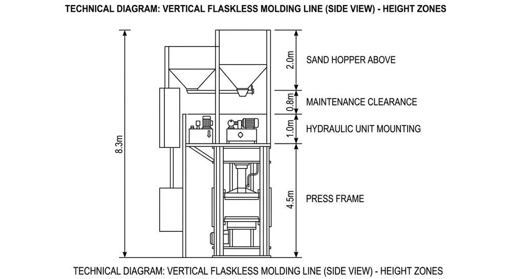
High-pressure molding lines (flaskless systems)
Flaskless lines typically run 8-12 bar because the mold has no flask for structural support. The sand itself must provide all the strength. Target hardness runs 90-95, and permeability becomes critical — you need sand with high green strength and high permeability, which usually means fresh sand with 9-10% active clay content.
(Note: if you're running a flaskless line and seeing blowhole problems, don't just reduce pressure — the molds will collapse during pouring. Fix permeability through sand reclamation or by increasing the percentage of fresh sand in your mix.)
PLC Parameter Adjustment Procedures
Modern automated molding lines use PLC control with adjustable squeeze pressure, dwell time, and pressure ramp rate. Here's how to adjust each parameter safely without creating new problems.
Squeeze pressure adjustment
Access the HMI touchscreen, navigate to "Molding Parameters" or "Squeeze Settings" (exact menu name varies by manufacturer). The pressure setpoint is usually labeled "Squeeze Pressure" or "Compaction Pressure" in bar or psi.
Make adjustments in 0.2 bar increments. After each adjustment, run three test molds and measure hardness before committing to production. Most systems have a "Test Mode" that runs a single cycle without advancing the conveyor — use this for pressure testing.
Document your changes. Write down the date, old pressure, new pressure, resulting hardness, and defect rate for the next 50 castings. If defect rate doesn't improve after 50 castings, revert to the previous setting and investigate other variables.
Dwell time adjustment
Dwell time is how long the squeeze plate holds pressure after reaching the setpoint. Standard dwell is 2-4 seconds. Increasing dwell time can improve hardness uniformity across the mold without increasing peak pressure.
If your mold hardness range is too wide (corners significantly softer than center), try increasing dwell time by 0.5-1.0 second before increasing pressure. This gives the sand more time to redistribute and compact evenly. Watch your cycle time — adding 1 second of dwell reduces your maximum molds per hour by 3-5%.
Pressure ramp rate
This controls how fast the squeeze plate applies pressure. Fast ramp (under 1 second to full pressure) can trap air in the sand and create weak spots. Slow ramp (over 3 seconds) reduces productivity.
Most lines run 1.5-2.5 second ramp. If you're seeing random weak spots in molds (hardness suddenly drops 20 points in a small area), try slowing the ramp rate. If molds are consistently uniform, leave ramp rate alone — it's not your problem.
Remote diagnostics and parameter tuning
TZFoundry molding lines with 4G remote diagnostics modules let you adjust these parameters without being on-site. Your maintenance team can log into the system, pull pressure logs, adjust setpoints, and monitor the next 10 cycles to verify the change worked. This cuts troubleshooting time from days (waiting for a technician to fly in) to hours.

Sand Compactability Testing as the Quality Control Feedback Loop
Compaction pressure optimization isn't a one-time setup task. Sand properties drift over time as clay degrades, moisture fluctuates, and contaminants accumulate. The feedback loop that keeps your pressure settings valid is regular sand testing, specifically the AFS 2210 compactability test.
Compactability measures how much strength the sand develops under standard compaction. It's expressed as a dimensionless number, typically 35-55 for production clay sand. When compactability drops below 40, your sand is losing its ability to form strong molds, and increasing compaction pressure won't fix it — you're trying to compress sand that doesn't have enough clay to bind.
Testing frequency
Run compactability tests daily on high-volume lines (over 100 molds per hour), weekly on lower-volume lines. Test both prepared sand before molding and returned sand after shakeout. The difference between the two tells you how much your sand is degrading per cycle.
If prepared sand reads 48 and returned sand reads 44, you're losing 4 points per cycle. After 10 cycles, your sand will be below 40 and you'll start seeing defects no matter what pressure you run. This signals that your Clay Sand Reclamation Line isn't recovering enough clay, or you need to increase fresh sand addition.
Using compactability data to adjust pressure
When compactability increases (fresh clay added, better reclamation), you can reduce compaction pressure and still maintain the same mold hardness. When compactability decreases, you need to either increase pressure or fix the sand — and there's a limit to how much pressure can compensate for bad sand.
We've seen foundries running 8.0 bar squeeze pressure trying to hit 85 hardness with sand that tested 38 compactability. They were destroying their molding machine (hydraulic cylinders failing every 6 months) and still getting defects. We ran the sand test, added 3% fresh bentonite clay, and dropped pressure back to 6.2 bar. Hardness went to 87 and defect rate dropped from 11% to 3%.
The lesson: sand testing tells you whether pressure adjustment will actually solve your problem or just mask it temporarily.
How Automated Molding Lines with Real-Time Pressure Monitoring Reduce Defect Rates
Manual molding lines rely on operator skill and periodic hardness checks to maintain quality. Automated PLC-controlled lines monitor squeeze pressure every cycle and flag deviations before they create defects.
Real-time pressure monitoring
Modern molding lines log actual squeeze pressure achieved for every mold. The system compares actual pressure to the setpoint and triggers an alarm if the deviation exceeds ±0.2 bar. This catches hydraulic system problems (leaking seals, failing pumps, clogged filters) before they affect casting quality.
On a manual line, you might run 50 defective molds before someone notices the pressure gauge reading low. On an automated line with real-time monitoring, the system stops after the first out-of-spec mold and alerts the operator.
Pressure profiling for complex molds
Some automated lines support multi-stage squeeze profiles: initial pressure to fill the flask, higher pressure for final compaction, then reduced pressure during dwell to prevent mold cracking. This gives you better control over hardness distribution in complex molds with deep pockets or thin walls.
We programmed a three-stage profile for a European buyer casting large pump housings: 4.0 bar initial fill, ramp to 7.5 bar for 2 seconds, then drop to 6.0 bar for 3-second dwell. This eliminated the mold cracking they were seeing with constant 7.5 bar pressure, while maintaining 86-88 hardness across the entire mold face.
Integration with sand testing equipment
The next level of automation connects your molding line PLC to your sand testing lab. When compactability drops below your threshold, the system automatically adjusts squeeze pressure to compensate, then sends an alert to the sand preparation operator to check clay content.
TZFoundry's in-house sand testing lab validates these control strategies before equipment ships. If you're buying a Clay Sand Processing Line configured for a specific casting type, we'll run your sand through the system, measure compactability and permeability, and program the optimal pressure profile into the PLC before the equipment leaves Qingdao.
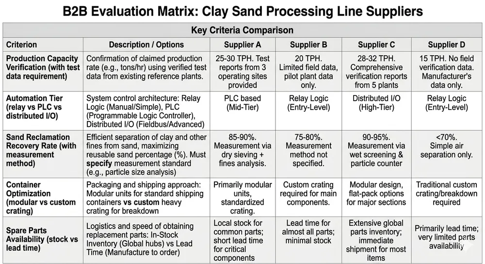
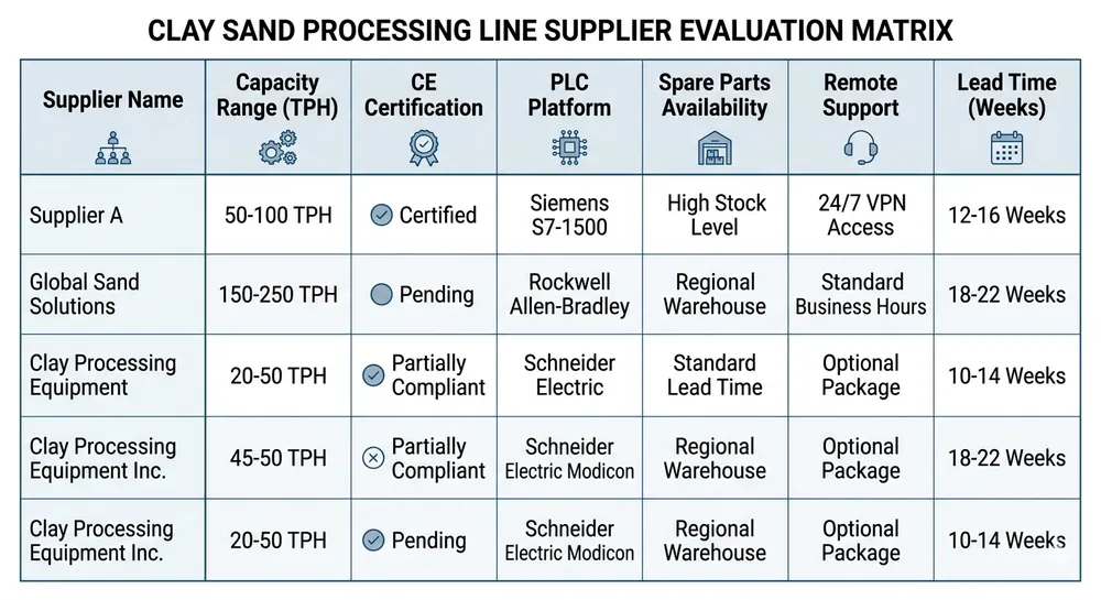
Selecting a Molding Line with Built-In Compaction Controls
If you're evaluating molding line suppliers, compaction control capability should be a primary selection criterion, not an afterthought. Here's what separates basic equipment from systems that actually prevent defects.
Closed-loop pressure control
The system must measure actual squeeze pressure achieved, not just command a target pressure. Hydraulic systems lose pressure due to seal wear, oil temperature changes, and valve drift. A closed-loop system adjusts the hydraulic flow to maintain the setpoint regardless of these variables.
Ask the supplier: "Does your system log actual pressure achieved for every mold, or just the setpoint?" If they can't show you pressure logs from a running installation, the control system isn't closed-loop.
Adjustable pressure parameters via HMI
You should be able to adjust squeeze pressure, dwell time, and ramp rate from the touchscreen without reprogramming the PLC or calling a technician. Production requirements change — you might switch from iron to aluminum castings, or start running larger molds. The equipment needs to adapt without a service visit.
Remote diagnostics capability
4G or Ethernet connectivity for remote parameter adjustment and troubleshooting. When defect rates spike at 2 AM, your maintenance team should be able to log in, check pressure logs, and adjust settings remotely. This matters more for export buyers — flying a technician from China to North America for a 30-minute parameter adjustment costs more than the remote diagnostics module.
Pressure uniformity across the mold
Ask about squeeze plate design and guide system precision. A worn or misaligned squeeze plate creates 15-20 point hardness variations across the mold face, and no amount of pressure adjustment fixes that. Look for:
- Four-corner guided squeeze plates (better than two-corner)
- Hardened guide pins and bushings (longer wear life)
- Squeeze plate flatness specification (should be within 0.2mm across the full plate)
Integration with sand testing feedback
This is rare but valuable: molding lines that accept input from automated sand testing equipment and adjust pressure accordingly. If your operation runs 24/7 with minimal supervision, automated feedback loops prevent the slow drift toward defects that happens when sand properties change and nobody notices for 8 hours.
TZFoundry's 18-engineer team calculates custom pressure profiles based on your casting alloy, mold dimensions, and sand properties. Send us your current defect rates and mold specifications — we'll recommend the molding line configuration and pressure settings that match your production requirements. Request a Quote to get started.

Baocun Zhu is the Senior Clay Sand Process Engineer at TZFoundry in Qingdao. With over 14 years commissioning clay sand molding, reclamation, and preparation lines for export foundries, he turns floor-space constraints and throughput targets into working production systems. His...