A vertical flaskless line that can't fit your building is a $200,000 mistake you discover after the deposit clears. Standard vertical flaskless configurations assume 8-meter ceilings — but plenty of industrial buildings in North America and Europe were built in the 1970s and 1980s with 6-7 meter clearances. If you're sourcing a vertical line for one of these facilities, you need to know what modifications keep your rated output intact and which compromises will cost you 15-20% throughput.
I've commissioned vertical flaskless lines in 14 countries over the past decade. The low-ceiling installations always follow the same pattern: buyers assume the equipment will "just fit" because the molding press itself is only 4.5 meters tall, then realize too late that the sand hopper, hydraulic unit mounting, and overhead maintenance access push the total height requirement to 7.8-8.2 meters. By the time they call us, they're either looking at expensive building modifications or trying to figure out how to reconfigure the line without killing cycle time.
This guide walks through the actual dimensional constraints, equipment placement decisions, and PLC adjustments that let you run a vertical flaskless line at rated capacity in a sub-8-meter facility.
Why Ceiling Height Becomes the Constraint
Vertical flaskless molding lines compress the mold vertically using a hydraulic press that moves up and down. The press frame, sand delivery system, and mold extraction mechanism all stack vertically — which is why these lines need less floor space than horizontal configurations but more overhead clearance.
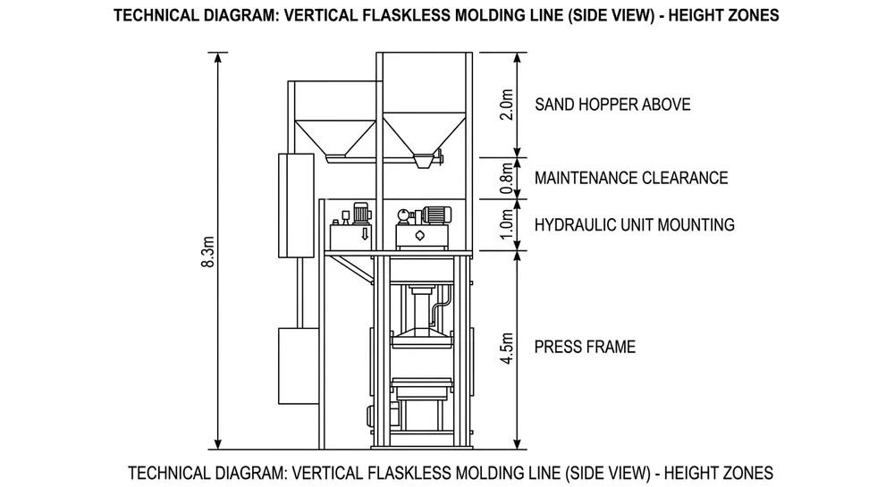
Here's where the 8-meter standard comes from:
- Molding press frame: 4.2-4.8m depending on mold size (this is the main structure)
- Sand hopper and delivery chute: 1.8-2.2m above the press (gravity-fed sand needs drop height for consistent fill)
- Hydraulic power unit mounting: typically roof-mounted or on an elevated platform, adding 0.8-1.2m
- Maintenance clearance above the press head: 0.5-0.8m minimum for accessing cylinders, replacing seals, adjusting limit switches
- Overhead crane hook height: if you're using a crane for mold handling, add another 0.5m
Total: 7.8-8.5 meters from floor to ceiling beam.
The problem isn't the press itself — it's the auxiliary equipment and access requirements stacked on top. When you try to force a standard configuration into a 6-meter building, you lose sand delivery efficiency (hopper too low = inconsistent fill weight), hydraulic unit access (can't reach the pump or pressure relief valve), and maintenance clearance (can't pull the top platen for seal replacement without disassembling half the line).
We've seen buyers try three bad workarounds:
- Cutting the sand hopper height — reduces sand volume, which means more frequent refills and lower effective cycle time
- Relocating the hydraulic unit to floor level — adds 6-8 meters of hydraulic hose, increasing pressure drop and slowing press stroke speed
- Skipping maintenance clearance — works until the first seal replacement, when you realize you need to rent a crane and cut a hole in the roof
None of these preserve your rated molds-per-hour output.

Step 1: Measure What Actually Matters
Before you contact any supplier, get these four measurements from your facility:
Floor-to-lowest-obstruction height — not just the ceiling. Measure to the bottom of any HVAC ducts, crane rails, sprinkler pipes, or electrical conduit. The lowest obstruction is your real ceiling height. We've had buyers quote us 7 meters and then discover a sprinkler main at 6.4 meters that nobody mentioned.
Floor load rating — vertical presses generate 150-200 tons of compaction force, which transfers directly to the floor. You need 8-12 tons per square meter depending on press size. If your floor is rated for 5 tons/m², you're either pouring a reinforced pad or looking at a different molding technology.
Overhead crane capacity and hook height — if you're using a crane for mold handling, we need to know the hook height at maximum lift. Some facilities have 10-ton cranes with only 5 meters of hook clearance, which doesn't leave enough room above the press for mold extraction.
Available pit depth — can you excavate? Some facilities sit on bedrock or have underground utilities that prevent digging. If you can go 0.5-1.0 meters below grade, that's 0.5-1.0 meters you don't need above the floor.
Send these four numbers in your RFQ. If you skip any of them, the layout drawing we send back will be wrong.
Step 2: Reconfigure the Sand Delivery System
The sand hopper is the easiest component to relocate without losing performance. Standard configurations mount the hopper directly above the press for gravity feed, but you can move it to the side and use a screw conveyor or pneumatic transfer to deliver sand horizontally into the press.
Side-mounted hopper with screw conveyor — hopper sits at floor level or on a 1-meter platform beside the press. A horizontal screw conveyor feeds sand into the press fill chamber. This cuts 1.8-2.0 meters from your total height requirement. The trade-off: screw conveyors add 2-3 seconds to your fill cycle because sand moves slower horizontally than it drops vertically. On a line rated for 80 molds/hour (45-second cycle), adding 3 seconds to the fill drops you to 75 molds/hour.
Pneumatic transfer with reduced-height hopper — hopper mounts at 1.2-1.5 meters instead of 2.0 meters, and a pneumatic blower pushes sand into the press. Faster than screw conveyors (adds only 1-2 seconds per cycle), but noisier and requires compressed air supply. You'll need 6-8 bar air pressure and about 2 m³/min flow rate.
We typically recommend screw conveyors for low-ceiling installs because the cycle time penalty is predictable and the system is mechanically simpler. Pneumatic transfer makes sense if you're already running compressed air for other equipment and can't tolerate any throughput loss.
(Note: if your target output is below 60 molds/hour, the screw conveyor penalty is negligible — you're not running at the edge of cycle time anyway.)
Step 3: Relocate the Hydraulic Power Unit
Standard vertical lines mount the hydraulic power unit on the press frame or on an overhead platform. This keeps hydraulic hoses short (under 3 meters), which minimizes pressure drop and maintains fast stroke speeds. In a low-ceiling facility, you need to move the unit down without killing press performance.
Floor-mounted hydraulic unit with reinforced hose routing — unit sits on the floor beside the press, connected via high-pressure hoses (typically 25-32mm diameter). You'll need 6-8 meters of hose to reach from floor level to the press cylinders. The pressure drop in 8 meters of 32mm hose at 150 bar is about 3-5 bar, which slows your press stroke by 8-12%. On a 45-second cycle, that's 4-5 seconds added per mold.
To compensate, we upsize the hydraulic pump from 40 L/min to 50 L/min and increase system pressure from 150 bar to 160 bar. This recovers most of the lost stroke speed — you'll end up with a 2-3 second penalty instead of 5 seconds. The pump upsize adds about $1,200 to the hydraulic unit cost.
Split hydraulic system — main power unit stays on the floor, but a small accumulator and manifold block mount directly on the press frame. The accumulator stores pressurized oil for the fast-stroke portion of the cycle, so you get full-speed pressing even with long hoses. The floor-mounted pump refills the accumulator between cycles. This configuration adds $2,800-3,500 to the hydraulic system cost but eliminates the cycle time penalty entirely.
For lines targeting 80+ molds/hour, the split system is worth it. For 60 molds/hour or lower, the upsized pump is sufficient.

Step 4: Adjust the Press Frame for Pit Installation
If your facility allows excavation, dropping the press base 0.5-1.0 meters below floor level is the simplest way to recover overhead clearance. The press foundation goes into a pit, and the mold extraction conveyor runs at floor level instead of elevated.
Pit depth calculation — for every 0.5 meters you go below grade, you gain 0.5 meters of overhead clearance. A 1-meter pit lets you fit a standard 8-meter configuration into a 7-meter building. The pit needs to be 3.5-4.0 meters wide (press footprint plus access space) and 4.5-5.0 meters long (press length plus conveyor clearance).
Pit construction requirements — reinforced concrete walls, waterproofing membrane, and sump pump for drainage. Budget $8,000-12,000 for pit construction depending on local labor rates. If you're in a high-water-table area, add another $3,000-5,000 for dewatering and drainage systems.
Maintenance access — you'll need removable floor grating or a permanent access ladder. Don't pour a solid floor over the pit — you need to get down there for hydraulic line inspection and cylinder seal replacement.
We've done pit installations in 6 facilities over the past 5 years. The construction cost is usually cheaper than the equipment modifications needed to avoid the pit, and you end up with a cleaner layout because the mold conveyor runs at floor level instead of elevated.
Step 5: Verify Maintenance Access Before Finalizing Layout
Low-ceiling configurations fail most often because buyers forget about maintenance access. You can fit the equipment into the building, but if you can't reach the top platen to replace hydraulic seals or adjust limit switches, the line becomes unserviceable.
Top platen access — you need 0.4-0.6 meters of clearance above the press head to remove the top platen for seal replacement. On a standard 8-meter line, this clearance is built in. On a 6-meter line with a 4.5-meter press, you're left with 1.5 meters above the press — which sounds like enough until you account for the sand hopper (even side-mounted hoppers have support brackets that overhang the press) and hydraulic hoses.
The fix: design the press frame with a removable top section. The upper 0.8-1.0 meters of the frame unbolts and lifts off with a crane or hoist, giving you full access to the platen and cylinders. This adds 2-3 hours to seal replacement time (because you're unbolting and re-bolting the frame), but it's better than discovering you can't service the press at all.
Hydraulic unit access — if the unit is floor-mounted, make sure there's 0.8-1.0 meters of clearance on at least two sides for pump replacement and filter changes. We've seen installations where the hydraulic unit gets wedged between the press frame and a wall, and the maintenance team can't reach the pump coupling or pressure relief valve.
Electrical cabinet placement — PLC cabinets and motor drives need front access for troubleshooting and rear access for cable entry. In tight layouts, buyers often push the cabinet against a wall to save floor space, then realize they can't open the rear panel to add I/O modules or replace a blown fuse.
Step 6: Tune PLC Parameters for Modified Cycle Times
Once the equipment is installed, you'll need to adjust the PLC program to account for the modified sand delivery and hydraulic system. Standard programs assume gravity-fed sand (instant fill) and short hydraulic hoses (fast stroke). If you've switched to screw conveyors and floor-mounted hydraulics, the timing is different.
Sand fill delay — if you're using a screw conveyor, add 2-3 seconds to the fill timer. The PLC needs to wait for the conveyor to deliver the full sand charge before starting the press stroke. If you start pressing too early, you'll get incomplete molds.
Press stroke speed adjustment — if you've upsized the hydraulic pump to compensate for long hoses, the stroke speed will be slightly faster than the standard program expects. Adjust the pressure ramp rate in the PLC to match the actual stroke speed — otherwise you'll get pressure spikes that trip the overload protection.
Mold extraction timing — if the press base is in a pit and the conveyor runs at floor level, the mold drop distance is shorter. Reduce the extraction delay by 1-2 seconds to keep the conveyor moving smoothly.
These adjustments take 30-45 minutes during commissioning. Our remote support team can walk your electrician through the parameter changes via video call — you don't need a PLC programmer on site.
Real-World Reference: TZFoundry's 6-Meter Ceiling Installation
We configured a vertical flaskless line for a buyer in Poland with a 6.2-meter ceiling in 2023. The facility was a converted warehouse built in 1985 — solid floor, no pit option, and a 5-ton overhead crane with 5.5 meters of hook clearance.
Configuration decisions:
- Side-mounted sand hopper with screw conveyor (saved 1.9m of height)
- Floor-mounted hydraulic unit with 50 L/min pump (saved 1.1m, added 3 seconds per cycle)
- Press frame height reduced from 4.8m to 4.3m by using a smaller mold size (buyer was running 500x400mm molds instead of 600x500mm)
- Total installed height: 5.8 meters from floor to top of press frame
Output results:
- Target: 70 molds/hour
- Actual: 68 molds/hour (3% below target due to screw conveyor fill time)
- Cycle time: 52 seconds (vs 48 seconds for standard configuration)
The buyer accepted the 3% throughput reduction because the alternative was a $45,000 building modification to raise the roof. The line has been running since March 2023 with no mechanical issues. Seal replacement takes 4 hours instead of the standard 2.5 hours because the maintenance team has to work around the side-mounted hopper, but that's a once-per-year task.

Common Mistakes That Kill Output in Low-Ceiling Installs
Underestimating ventilation clearance — vertical presses generate heat from hydraulic oil and friction. You need 0.3-0.5 meters of clearance around the hydraulic unit for airflow. In tight layouts, buyers pack equipment too close together and the hydraulic oil overheats, triggering thermal shutdowns that stop production.
Ignoring crane interference — if your overhead crane rail runs at 6 meters and your press frame is 4.5 meters tall, you only have 1.5 meters of clearance for the crane hook and mold lifting. That's not enough if you're handling 500x500mm molds (which are 0.3-0.4m tall). The crane hook hits the press frame during mold extraction. The fix: offset the press 1-2 meters from the crane rail centerline, or use a side-pull extraction system instead of overhead lifting.
Skipping the floor load check — vertical presses concentrate 150-200 tons of force on a 2×2 meter footprint. That's 18-25 tons per square meter. Standard industrial floors are rated for 5-8 tons/m². If you install the press without reinforcing the floor, you'll get concrete cracking and foundation settlement within 6 months. Budget $6,000-10,000 for a reinforced concrete pad under the press.
Using the wrong mold size — buyers sometimes try to run 600x500mm molds in a low-ceiling configuration. Larger molds need taller press frames (more stroke length), which pushes your total height back up. If ceiling height is your constraint, consider dropping to 500x400mm or 450x400mm molds. You'll run more molds per casting (because each mold is smaller), but your cycle time stays manageable and the equipment fits.
What to Include in Your RFQ When Ceiling Height Is a Constraint
Send your supplier these seven data points:
- Floor-to-lowest-obstruction height (measured, not estimated)
- Floor load rating in tons per square meter
- Available pit depth (or "no excavation allowed")
- Overhead crane capacity and hook height (if applicable)
- Target mold output in molds per hour
- Mold size you plan to run (length x width in mm)
- Compressed air availability (pressure and flow rate, if you have it)
With these numbers, an engineering team can produce a custom layout showing whether a vertical flaskless line fits your space, what modifications are needed, and what the realistic output rate will be after modifications.
Don't send a generic "we have a 6-meter ceiling, can you fit a vertical line?" inquiry. The answer is always "maybe" — which doesn't help you make a sourcing decision. Send the actual dimensions and constraints, and ask for a dimensioned layout drawing with cycle time projections.
When a Vertical Line Doesn't Make Sense
If your ceiling is below 6 meters and you can't excavate, a vertical flaskless line probably isn't the right choice. The equipment modifications needed to fit a 5.5-meter space will cost more than switching to a horizontal flaskless configuration, which only needs 3.5-4.0 meters of ceiling clearance.
Horizontal lines take up more floor space (12-15 meters long vs 6-8 meters for vertical), but they're easier to service and don't require overhead crane access. If you have the floor space but not the ceiling height, go horizontal.
The break-even point is around 6.2-6.5 meters of ceiling clearance. Above that, vertical lines work with manageable modifications. Below that, you're fighting the equipment's fundamental design.
Next Steps
If you're evaluating a vertical flaskless line for a facility with limited ceiling height, send TZFoundry your floor-to-ceiling measurement, floor load rating, and target mold output. Our engineering team will provide a custom layout drawing showing whether the line fits your space, what modifications are needed, and what the realistic cycle time will be after adjustments.
We've configured vertical lines for 6-meter ceilings, 6.5-meter ceilings, and one 5.8-meter facility (that one required a 0.8-meter pit). The layout process takes 3-5 business days once we have your facility dimensions.
For more details on standard vertical flaskless line specifications, see our Vertical Flaskless Clay Sand Processing Line page. If you're comparing vertical vs horizontal configurations, our Clay Sand Processing Line category page covers the trade-offs.
Request a custom layout drawing with your facility dimensions and target output rate.

Baocun Zhu is the Senior Clay Sand Process Engineer at TZFoundry in Qingdao. With over 14 years commissioning clay sand molding, reclamation, and preparation lines for export foundries, he turns floor-space constraints and throughput targets into working production systems. His...