The porosity you see in a finished casting started at the foam pattern. So did the carbon inclusions, the misruns, and the dimensional drift. I've spent 12 years troubleshooting lost foam lines, and the pattern is where most defects originate — not at the coating stage, not at the vacuum chamber, but earlier.
Most buyers focus on the casting equipment and treat foam patterns as a commodity input. They specify "EPS pattern" in the purchase order and assume suppliers know what that means. They don't. EPS density can range from 16 to 32 kg/m³. Bead size varies from 0.3 to 2.0 mm. Dimensional tolerance classes span ±0.3 mm to ±2.0 mm. Each combination produces different burn-out residue, surface finish, and pattern rigidity — which directly affect your casting yield.
This article explains which foam pattern specs to lock down before you place an order, and how each parameter connects to the defects you're trying to avoid.
Why Foam Pattern Specs Matter More Than Most Buyers Realize
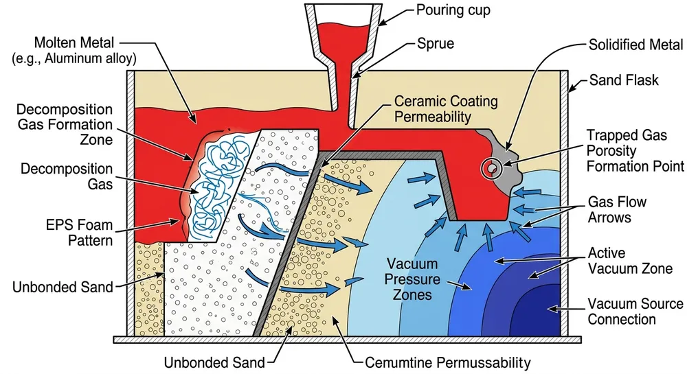
Lost foam casting eliminates the need for cores and parting lines, but it trades those complexities for a different risk: the pattern must vaporize cleanly under molten metal without leaving residue that causes porosity or carbon defects. If your pattern supplier ships 18 kg/m³ foam when your process needs 22 kg/m³, the pattern collapses during coating application. If they send 1.5 mm bead size when your surface finish spec requires 0.5 mm, you'll spend hours grinding castings that should have come out clean.
We've commissioned lost foam lines in 14 countries. The most common production failure isn't vacuum system leaks or coating thickness variation — it's pattern spec mismatch. A Middle Eastern ductile iron foundry ran three months at 68% yield before we traced the problem to foam density. Their pattern supplier was delivering 19 kg/m³ foam for 25 mm wall sections that needed 24 kg/m³. The patterns survived coating but deformed under sand compaction, causing dimensional drift and misruns.
The fix wasn't equipment adjustment. It was rewriting the pattern purchase order with measurable specs.
EPS Foam Pattern Density: The Primary Defect Control Variable
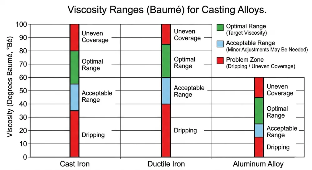
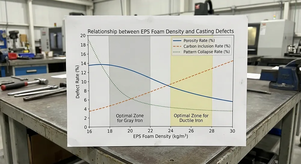
Density determines how much polymer mass vaporizes per unit volume when molten metal contacts the pattern. Higher density means more gas generation, which requires stronger vacuum draw to evacuate. Lower density means less rigidity, which risks pattern collapse during handling or coating.
Standard lost foam practice uses 20–24 kg/m³ for most ferrous castings. That range works for gray iron and ductile iron parts with 10–40 mm wall thickness. But it's not universal.
Density Selection by Alloy and Wall Thickness
| Alloy Type | Wall Thickness | Recommended Density (kg/m³) | Reason |
|---|---|---|---|
| Gray iron | 8–15 mm | 20–22 | Thin walls need lower gas volume to prevent blowback |
| Gray iron | 15–40 mm | 22–24 | Standard range for most production |
| Ductile iron | 10–25 mm | 23–25 | Higher carbon content requires stronger vacuum draw |
| Aluminum alloys | 3–10 mm | 18–20 | Lower pouring temperature allows lighter patterns |
| Steel castings | 15–50 mm | 24–28 | High superheat demands maximum pattern rigidity |
We run TZFoundry's Lost Foam Casting Production Line systems across an 18–28 kg/m³ density range — wider than the industry-standard 20–24 kg/m³. This gives you flexibility when your casting mix includes both thin-wall aluminum housings and heavy-section steel brackets. The vacuum system adjusts from -0.04 to -0.08 MPa to match pattern density, and the PLC-controlled coating line compensates for density variation by adjusting dip time and drainage angle.

What Happens When Density Is Wrong
Too low (below 18 kg/m³): Pattern deforms during coating application. We've seen patterns sag 3–5 mm on horizontal surfaces after the second coating dip. By the time the pattern reaches the sand flask, dimensional accuracy is gone. You'll also get pattern breakage during handling — a 20 kg aluminum casting pattern at 16 kg/m³ density cracks if you lift it by a thin rib section.
Too high (above 28 kg/m³): Excessive gas generation during metal pour. If your vacuum system can't evacuate fast enough, gas pressure builds between the pattern and the coating shell, causing blowback defects or incomplete fills. We tested 30 kg/m³ patterns on a ductile iron line rated for -0.06 MPa vacuum. Porosity rate jumped from 4% to 19% because the system couldn't handle the gas load.
The in-house sand reclamation testing lab at our facility runs burn-out tests on sample patterns before full production. We measure residual carbon content in the sand after pattern vaporization. If your pattern supplier can't provide density certification within ±1 kg/m³, you're guessing.
Bead Size: Surface Finish and Detail Reproduction
EPS foam is made by expanding polystyrene beads under steam pressure, then fusing them in a mold. Bead size determines surface texture on the finished pattern, which transfers directly to the casting surface.
Smaller beads produce smoother surfaces. Larger beads fuse faster and cost less, but leave a rougher texture that shows up as surface porosity on the casting.
Bead Size to Surface Finish Reference
| Bead Size (mm) | Pattern Surface Roughness (Ra, μm) | Casting Surface Finish (Ra, μm) | Best Application |
|---|---|---|---|
| 0.3–0.5 | 12–18 | 25–35 | Precision aluminum parts, visible surfaces |
| 0.5–0.8 | 18–28 | 35–50 | Standard gray iron and ductile iron castings |
| 0.8–1.2 | 28–45 | 50–75 | Heavy-section steel castings, non-critical surfaces |
| 1.2–2.0 | 45–80 | 75–120 | Large structural castings, machined-all-over parts |
If your casting requires Ra 40 μm or better as-cast, specify 0.5 mm maximum bead size in the pattern purchase order. If the part gets machined all over, you can use 1.2 mm beads and save 15–20% on pattern cost.
We've seen buyers specify 0.3 mm beads for castings that get sandblasted and powder-coated. That's wasted money. The coating process obliterates any surface finish advantage from fine beads. Save the tight bead spec for parts where surface texture affects function — sealing surfaces, bearing bores, aesthetic components.
Bead Fusion Quality Matters More Than Bead Size
A poorly fused 0.5 mm bead pattern performs worse than a well-fused 0.8 mm pattern. Incomplete bead fusion creates weak points where the pattern cracks during handling or coating. It also creates micro-voids that trap air, which shows up as pinhole porosity on the casting.
When you evaluate a pattern supplier, break a sample pattern and look at the cross-section. The beads should be fused into a continuous structure with no visible gaps. If you can pull individual beads apart with your fingers, the fusion cycle was too short or the steam pressure was too low. That pattern will fail in production.
Dimensional Tolerance: How Pattern Accuracy Translates to Casting Accuracy
Lost foam patterns shrink during cooling after they're removed from the mold. EPS shrinks about 0.5–0.8% as it cools from 110°C (steam molding temperature) to room temperature. The pattern supplier should account for this in the mold design, but not all do.
Then the pattern expands slightly during coating application as it absorbs moisture. Then it compresses under sand compaction pressure in the flask. Each step introduces dimensional variation.
Your final casting accuracy depends on how tightly the pattern supplier controls these variables.
Pattern Tolerance Classes
| Tolerance Class | Dimensional Accuracy (mm) | Typical Application | Pattern Cost Multiplier |
|---|---|---|---|
| CT10 | ±0.3 | Precision aluminum housings, tight-fit assemblies | 1.8–2.2× |
| CT11 | ±0.5 | Standard ductile iron parts, moderate fit requirements | 1.3–1.5× |
| CT12 | ±0.8 | Gray iron castings, general industrial use | 1.0× (baseline) |
| CT13 | ±1.2 | Large steel castings, machined-all-over parts | 0.8–0.9× |
| CT14 | ±2.0 | Structural castings, rough blanks | 0.7× |
Most buyers don't specify tolerance class. They write "standard tolerance" in the purchase order and assume the supplier knows what that means. Standard for one supplier is CT12. Standard for another is CT14. You won't know until the first batch of castings comes back 1.5 mm oversize.
We recommend specifying CT11 (±0.5 mm) for most ferrous castings unless you have a specific reason to go tighter or looser. CT10 requires secondary machining on the pattern mold itself, which adds cost and lead time. CT13 and CT14 are fine for rough castings, but you'll spend the savings on extra machining stock removal.

Shrinkage Allowance: The Spec Most Buyers Forget
The pattern must be oversized to compensate for metal solidification shrinkage. Gray iron shrinks 0.8–1.0%. Ductile iron shrinks 1.0–1.2%. Aluminum alloys shrink 1.2–1.5%. Steel shrinks 1.5–2.0%.
Your pattern supplier should build this allowance into the pattern mold. But if you don't specify the alloy and the target casting dimensions, they'll guess. We've seen pattern suppliers use 1.0% shrinkage allowance for aluminum castings that needed 1.3%, resulting in castings that were 3 mm undersize on a 1000 mm length.
When you send a pattern RFQ, include:
- Alloy composition (not just "aluminum" — specify 356, A380, etc.)
- Final casting dimensions with tolerances
- Machining stock allowances if applicable
The pattern supplier should send back a pattern dimension drawing that shows the shrinkage allowance calculation. If they don't, they're not doing the math.
Specification Checklist: What to Lock Down in Your Pattern Purchase Order
Most pattern-related casting defects trace back to incomplete purchase orders. Buyers specify the part geometry and assume the supplier will figure out the rest. They won't — or they'll make assumptions that don't match your process.
Here's what to specify:
Material specs:
- EPS density (kg/m³) with ±1 kg/m³ tolerance
- Bead size range (mm)
- Bead fusion quality standard (specify test method or reference sample)
Dimensional specs:
- Tolerance class (CT10, CT11, CT12, etc.) or absolute tolerance in mm
- Shrinkage allowance percentage for your specific alloy
- Critical dimensions that must be held tighter than general tolerance
- Datum references for dimensional inspection
Quality verification:
- Density certification method (water displacement, mass/volume calculation)
- Dimensional inspection report format (CMM, manual measurement, etc.)
- Sample pattern approval before full production run
- Batch traceability (pattern lot number marked on each pattern)
Handling and packaging:
- Maximum stacking height to prevent compression damage
- Packaging method (individual boxes, foam-lined crates, etc.)
- Storage temperature range (EPS degrades above 40°C)
We've worked with foundries that run Lost Foam Casting Equipment from three different pattern suppliers. The ones with detailed purchase orders get consistent quality. The ones that send a CAD file and say "quote this" get patterns that vary 15–20% in density batch-to-batch.
How TZFoundry's Production Line Handles Pattern Variation
Even with tight pattern specs, you'll get some batch-to-batch variation. A good lost foam production line compensates for minor pattern differences through process control.
Our PLC-controlled coating system adjusts dip time based on pattern density. Lower-density patterns (18–20 kg/m³) get 8–12 seconds in the coating tank. Higher-density patterns (24–28 kg/m³) get 15–20 seconds. The drainage angle adjusts automatically to maintain 0.8–1.2 mm coating thickness regardless of pattern surface texture.
The vacuum system monitors pressure in real time during metal pour. If pattern density is higher than expected (more gas generation), the system increases vacuum draw from -0.05 MPa to -0.07 MPa within 2 seconds. This prevents gas backpressure that causes porosity.
We can't fix a pattern that's 5 mm out of tolerance or made from 15 kg/m³ foam when the process needs 24 kg/m³. But we can handle the normal variation you get from a competent pattern supplier — ±1 kg/m³ density, ±0.1 mm bead size, ±0.3 mm dimensional drift.
The Lost Foam Casting Foam Coating system includes a pattern pre-inspection station where operators check five patterns per batch with a handheld density meter and digital calipers. If a batch falls outside spec, it gets flagged before coating. That's cheaper than finding out after you've poured 200 castings.
Common Sourcing Mistakes and How to Avoid Them
Mistake 1: Treating all EPS foam as equivalent
Buyers see "EPS pattern" in two supplier quotes and assume they're comparing the same thing. One supplier is quoting 20 kg/m³ with 0.8 mm beads at CT12 tolerance. The other is quoting 18 kg/m³ with 1.2 mm beads at CT13 tolerance. The second quote is 25% cheaper, but you'll spend that difference on rework and scrap.
Ask for density certification and bead size specification in writing before you compare prices.
Mistake 2: Not testing pattern burn-out behavior before production
Pattern suppliers can hit the density spec and still deliver foam that leaves excessive carbon residue. This happens when the EPS resin contains too much flame retardant or when the bead expansion process isn't optimized.
Request a burn-out test before you commit to a large order. We run this test in our sand reclamation lab: place a pattern sample in a crucible, heat to 750°C (typical gray iron pouring temperature), and measure residual carbon in the ash. It should be below 2% by mass. Above 3%, you'll get carbon inclusions in the casting.
Mistake 3: Ignoring pattern storage conditions
EPS degrades under UV exposure and high temperature. Patterns stored outdoors in summer heat (above 40°C) lose 10–15% rigidity within two weeks. They'll survive coating but deform under sand compaction.
Specify indoor storage at 15–25°C in your purchase order. If your pattern supplier doesn't have climate-controlled storage, find a different supplier.
Mistake 4: Not linking pattern specs to casting defect data
Most foundries track casting defect rates but don't correlate them back to pattern batch numbers. When porosity rate jumps from 3% to 12%, they adjust vacuum pressure or coating thickness. They don't check if the pattern supplier changed foam density.
Mark each pattern batch with a lot number. Track that number through coating, pouring, and final inspection. When defect rates change, you'll know whether it's a pattern issue or a process issue.
Decision Guide: Matching Pattern Specs to Your Casting Requirements
For thin-wall aluminum castings (3–10 mm wall thickness):
- Density: 18–20 kg/m³
- Bead size: 0.3–0.5 mm
- Tolerance: CT10 or CT11 (±0.3 to ±0.5 mm)
- Shrinkage allowance: 1.3–1.5%
For standard gray iron and ductile iron parts (10–40 mm wall thickness):
- Density: 22–24 kg/m³
- Bead size: 0.5–0.8 mm
- Tolerance: CT11 or CT12 (±0.5 to ±0.8 mm)
- Shrinkage allowance: 0.8–1.2%
For heavy-section steel castings (15–50 mm wall thickness):
- Density: 24–28 kg/m³
- Bead size: 0.8–1.2 mm
- Tolerance: CT12 or CT13 (±0.8 to ±1.2 mm)
- Shrinkage allowance: 1.5–2.0%
For large structural castings (machined-all-over):
- Density: 22–26 kg/m³ (match to alloy type)
- Bead size: 1.2–2.0 mm (surface finish doesn't matter)
- Tolerance: CT13 or CT14 (±1.2 to ±2.0 mm)
- Shrinkage allowance: per alloy specification
If you're setting up a new lost foam line or switching pattern suppliers, start with a 50-pattern trial batch. Run them through your full process and measure yield, dimensional accuracy, and surface finish. Don't commit to a 5,000-pattern order until you've validated the specs in production.

Next Steps
If you're evaluating lost foam casting equipment or need to configure a production line for specific pattern specs, send us your casting alloy, wall-thickness range, and target surface-finish requirements. Our engineering team will recommend the matching foam pattern specifications and configure a Lost Foam Casting Production Line quote with vacuum and coating systems sized for your pattern density range.
We handle EPS densities from 18–28 kg/m³ and can validate pattern burn-out behavior in our sand reclamation testing lab before you commit to full production. Request a quote with your casting specifications and current pattern supplier details — we'll review your specs and identify any gaps that could cause defects.

Zhang Peng leads lost foam casting systems at TZFoundry, where he has spent over 12 years engineering vacuum casting lines, coating systems, and foam pattern equipment for export foundries. He specializes in defect prevention and yield optimization across cast iron...