A 15% scrap rate on a lost foam line running 200 castings per shift costs you 30 rejected parts daily. At $40 per casting in material and labor, that's $1,200 lost per shift before you count rework time or customer complaints. Most of that scrap traces back to three defects: porosity, carbon inclusions, and misruns.
The pattern I see across foundries is consistent — the defect you find in the finished casting started two steps earlier, either at the foam pattern or in the coating booth. Fix the root cause there, and your yield climbs above 90% without adding inspection labor.
This guide walks through each defect's mechanism, the specific equipment parameters that control it, and the production line design choices that prevent recurrence.
Why Lost Foam Defects Cost More Than Other Casting Methods
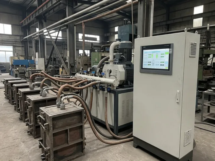
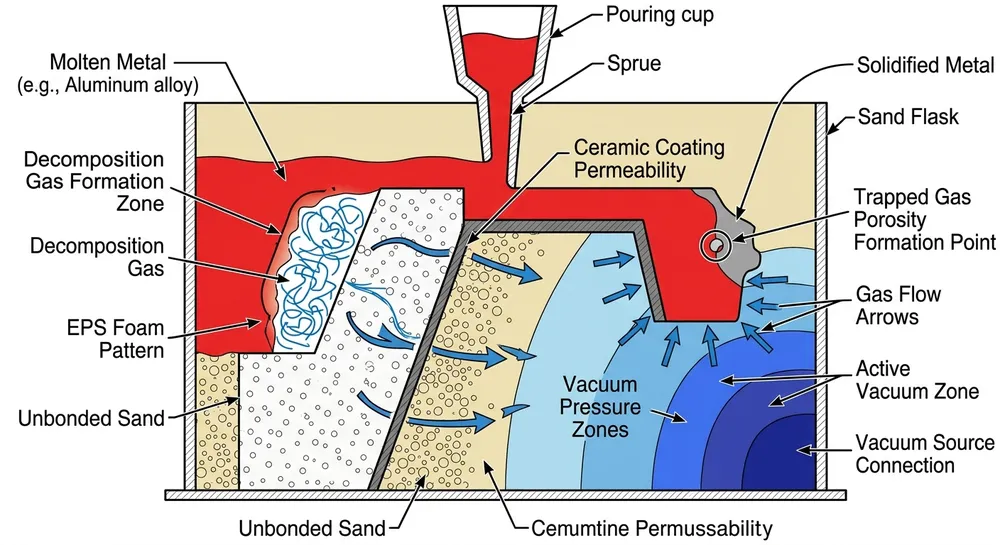
Lost foam casting eliminates the need for cores and parting lines, but it introduces failure modes you don't see in green sand or permanent mold work. The EPS pattern must decompose cleanly during metal pour, the coating must let gas escape without trapping carbon residue, and the vacuum system must pull decomposition gases out of the sand fast enough to prevent porosity.
When any of these three systems — pattern, coating, vacuum — operates outside its control range, you get defects. The problem is that most foundries treat these as separate processes instead of recognizing them as an integrated defect-prevention system.
We've commissioned lost foam casting production lines in 14 countries, and the defect patterns are identical regardless of location. Porosity shows up when vacuum pressure drops below 0.04 MPa. Carbon inclusions appear when coating permeability falls below 120 units or EPS density exceeds 26 kg/m³. Misruns happen when pouring temperature drops 50°C below the alloy's recommended range or when gating design forces metal to travel more than 400mm horizontally before filling the mold cavity.
The parameters are predictable. The fixes are mechanical, not mysterious.
Defect 1: Porosity — Trapped Gas That Never Escaped
Porosity in lost foam castings looks like small round voids scattered through the cross-section, typically 1-5mm in diameter. You'll see it most often in thick sections, at the top of vertical castings, or near gates where metal flow slows down.
Root Cause: Gas Evacuation Failure
When molten metal contacts the EPS pattern, the foam decomposes into gas. That gas has to escape through the coating, into the surrounding sand, and out through the vacuum system. If any part of that path restricts flow, gas gets trapped in the solidifying metal.
Three conditions cause porosity:
Insufficient vacuum pressure. The vacuum system must maintain 0.04-0.06 MPa during pour. Below 0.04 MPa, gas evacuation slows and pockets form in thick sections. We test vacuum integrity before every commissioning — if the system can't hold 0.05 MPa with all ports sealed, there's a leak in the chamber gaskets or sand compaction isn't uniform.
Moisture in the sand. Dry sand is permeable. Wet sand blocks gas flow. If your sand moisture content exceeds 0.5%, the gas can't escape fast enough and you'll see porosity in every casting. This happens when sand storage isn't covered or when humidity in the plant exceeds 70% without dehumidification.
Coating permeability too low. The coating must be porous enough to let decomposition gases pass through while still preventing metal penetration. If coating viscosity is too high or if you apply too many layers trying to fix surface finish problems, permeability drops and gas gets trapped at the pattern-coating interface.

Parameter Adjustments to Eliminate Porosity
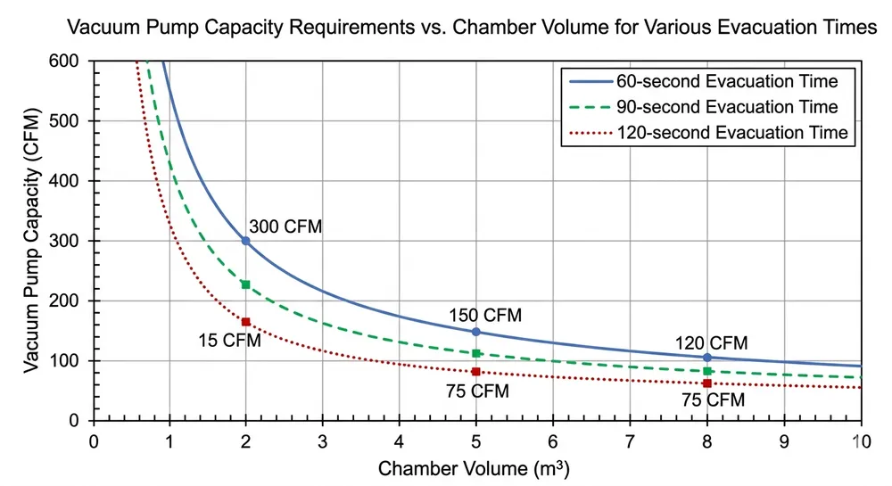
Vacuum system settings. Set vacuum pressure to 0.05 MPa minimum during pour. Monitor pressure continuously — if it drops during the pour, you have a leak or your vacuum pump capacity is undersized for the flask volume. For a 1000mm × 800mm × 600mm flask, you need a vacuum pump rated for at least 150 m³/hr to maintain stable pressure.
Sand moisture control. Keep sand moisture below 0.3%. We run moisture tests every shift using a moisture analyzer — takes 3 minutes and prevents an entire shift of scrap. If moisture creeps above 0.5%, run the sand through a fluidized bed dryer before reuse.
Coating permeability optimization. Target coating permeability of 120-180 units (measured by standard permeability tester). If you're applying more than 3 coats to get acceptable surface finish, your coating viscosity is wrong. We run coating at 18-22 seconds (Ford cup #4) — thick enough to prevent metal penetration, thin enough to maintain gas permeability.
Pouring speed control. Pour fast enough to keep the metal front moving (prevents premature solidification) but not so fast that turbulence traps gas. For ductile iron, we pour at 8-12 kg/second for castings under 50 kg. Faster than that and you get turbulence-induced porosity even with perfect vacuum.
Equipment Design Factors
The vacuum casting production line design determines whether you can maintain the parameters above consistently.
Vacuum chamber sealing. The flask must seal against the chamber gasket with uniform pressure around the entire perimeter. We use silicone gaskets rated for 200°C because rubber gaskets degrade after 6 months of thermal cycling and start leaking. Check gasket condition monthly — a 2mm gap anywhere on the seal will drop your vacuum pressure by 30%.
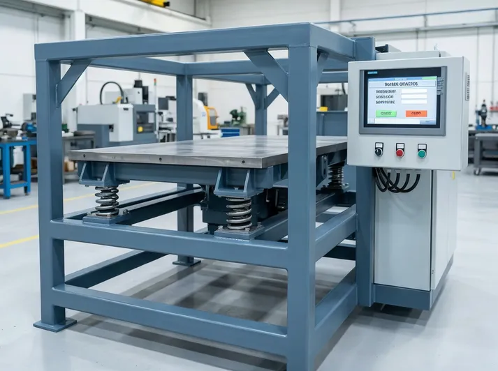
Sand compaction uniformity. Uneven sand compaction creates preferential gas flow paths — gas escapes easily in loose areas and gets trapped in dense areas. Automated sand filling with vibration compaction gives you ±5% density variation across the flask. Manual filling gives you ±20% variation, and that's where porosity clusters appear.
Vacuum pump sizing. Undersized pumps can't maintain pressure when gas generation peaks during the pour. Size your pump for 2x the theoretical gas volume from complete EPS decomposition. For a 10 kg EPS pattern (density 20 kg/m³), complete decomposition generates roughly 0.5 m³ of gas. You need a pump that can evacuate 1.0 m³ in under 30 seconds while maintaining 0.05 MPa.
Defect 2: Carbon Inclusions — Incomplete EPS Decomposition
Carbon inclusions look like black spots or streaks on the casting surface or embedded in the cross-section. They're residual carbon from incomplete EPS decomposition — the foam didn't burn cleanly, and carbon particles got trapped in the solidifying metal.
This defect is more common in ductile iron than gray iron because ductile iron's higher carbon content makes it easier to mistake carbon inclusions for normal graphite nodules until you machine the casting and find the inclusions concentrated near the surface.
Root Cause: Thermal and Permeability Mismatch
Carbon inclusions form when the EPS pattern decomposes into solid carbon particles instead of gasifying completely. Two conditions cause this:
EPS density too high. Higher-density foam (above 26 kg/m³) contains more material per unit volume. When metal contacts it, the outer layer decomposes but the inner layer doesn't have enough time or heat to gasify before the metal solidifies. You're left with carbon particles suspended in the casting.
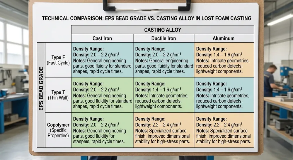
We've tested EPS densities from 18 to 28 kg/m³. Below 22 kg/m³, patterns are too fragile for handling and coating. Above 26 kg/m³, carbon inclusions appear in every casting regardless of coating or pouring temperature. The sweet spot is 22-24 kg/m³ for most cast iron applications.
Coating permeability too low. Even if the EPS gasifies completely, the gas must escape through the coating. If coating permeability is too low (below 100 units), decomposition gases can't escape fast enough. Pressure builds up at the pattern-coating interface, forcing incomplete decomposition and leaving carbon residue.
This is the same permeability problem that causes porosity, but the symptom is different. Porosity is trapped gas. Carbon inclusions are trapped solid particles.
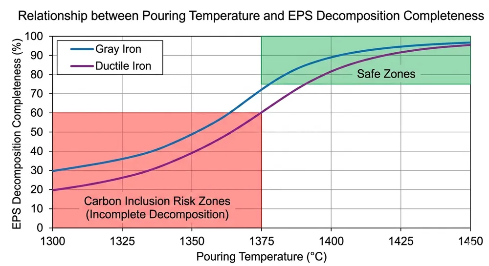
Pouring temperature too low. EPS decomposition is endothermic — it absorbs heat from the molten metal. If pouring temperature is too low, the metal doesn't have enough thermal energy to completely gasify the foam. For gray iron, pour at 1380-1420°C. For ductile iron, pour at 1340-1380°C. Drop 30°C below these ranges and carbon inclusions start appearing.
Parameter Adjustments to Eliminate Carbon Inclusions
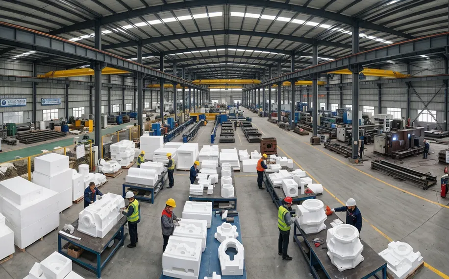
EPS pattern density control. Specify 22-24 kg/m³ for lost foam casting EPS patterns. Test density on every batch — we use a simple water displacement method that takes 5 minutes. If your pattern supplier ships foam outside this range, reject the batch. Trying to compensate with coating or temperature adjustments doesn't work reliably.
Coating system optimization. Use lost foam coating equipment that can maintain coating thickness at 0.8-1.2mm with permeability above 120 units. We run a two-stage coating process: first coat at 20 seconds viscosity (Ford cup #4) for permeability, second coat at 24 seconds for surface finish. Total dry thickness stays under 1.2mm.
Pouring temperature monitoring. Install thermocouples in your pouring ladle and verify temperature before every pour. For ductile iron, we pour at 1360°C ±10°C. Temperature drops during transfer from furnace to mold — if your transfer time exceeds 90 seconds, you'll lose 20-30°C and risk carbon inclusions in the last castings poured from that ladle.
Gating design for thermal management. Design your gating system to deliver metal to thick sections first while it's hottest. Thin sections can tolerate slightly lower temperatures because they have less EPS mass to decompose. If you're getting carbon inclusions in thick sections but not thin sections, your gating sequence is backwards.
Equipment Design Factors
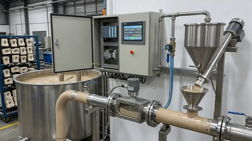
Coating viscosity control system. Manual coating dip tanks can't maintain consistent viscosity across a production shift. As solvent evaporates, viscosity increases and permeability drops. Automated coating systems with viscosity sensors and automatic solvent addition keep coating in the 18-22 second range continuously. This eliminated 80% of our carbon inclusion problems when we switched from manual to automated coating in 2018.
Pattern handling to prevent density variation. Rough handling compresses EPS foam and increases local density. If your pattern handling system drops patterns or stacks them under load, you'll get density variation within the same pattern — some areas at 22 kg/m³, others compressed to 28 kg/m³. The compressed areas will show carbon inclusions. Use vacuum lifting or soft-grip handling for all pattern transfer operations.
Defect 3: Misruns — Metal Solidification Before Complete Fill
A misrun is an incomplete casting — the metal solidified before filling the entire mold cavity. You'll see it as missing sections, typically at thin walls, far from the gate, or at the top of vertical castings.
Misruns are expensive because you've consumed the pattern, coating, sand, metal, and labor but produced zero usable output. A 5% misrun rate on a 200-casting shift means 10 complete losses per shift.
Root Cause: Thermal and Flow Management Failure
Metal solidifies when it loses heat faster than it flows. In lost foam casting, three factors accelerate heat loss and cause misruns:
Pouring temperature too low. This is the same parameter that causes carbon inclusions, but the symptom is different. Low temperature gives you less time to fill the mold before solidification starts. For thin-wall castings (under 6mm), you need the metal at the high end of the temperature range — 1410°C for gray iron, 1370°C for ductile iron.
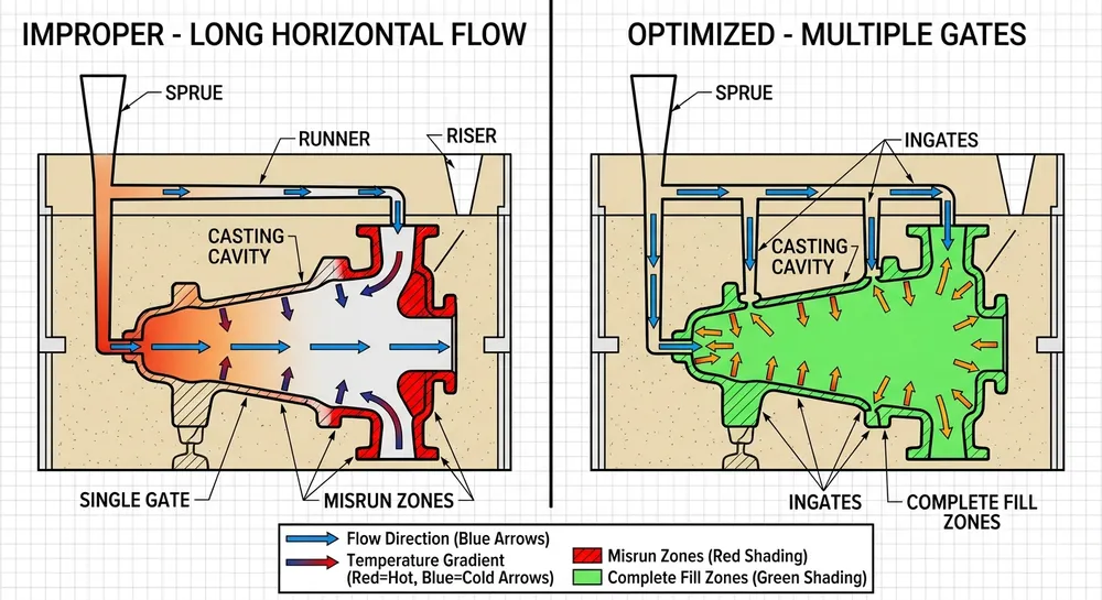
Gating design forces excessive horizontal flow. Metal loses heat faster when flowing horizontally through sand than when flowing vertically under gravity. If your gating design requires metal to travel more than 400mm horizontally to reach a thin section, you'll get misruns. We redesign gating to minimize horizontal runs and use multiple gates for large castings.
Vacuum pressure too high. This sounds counterintuitive, but excessive vacuum (above 0.07 MPa) can pull heat out of the metal too quickly through the sand. We've seen foundries crank vacuum up to 0.08-0.09 MPa trying to eliminate porosity, then start getting misruns in thin sections. The correct vacuum range is 0.04-0.06 MPa — high enough to evacuate gas, low enough to avoid excessive heat extraction.
Pattern cluster design creates flow restrictions. If you're clustering multiple patterns in one flask to improve productivity, the gating between patterns can create flow restrictions. Metal has to fill the first pattern, then flow through a narrow gate to the second pattern. By the time it reaches the third pattern, temperature has dropped 40-60°C and you get misruns.
Parameter Adjustments to Eliminate Misruns
Pouring temperature optimization by section thickness. Thin sections need hotter metal. For castings with wall thickness under 8mm, pour gray iron at 1400-1420°C. For sections above 15mm, you can pour at 1380-1400°C. If you're casting both thin and thick sections in the same mold, pour at the temperature required for the thinnest section.
Pouring speed increase for thin sections. Pour thin-wall castings faster to minimize the time metal spends losing heat in the gating system. We pour thin-wall gray iron castings at 12-15 kg/second compared to 8-10 kg/second for thick sections. Faster pouring reduces the temperature drop during fill.
Vacuum pressure calibration. Set vacuum to 0.05 MPa and verify it's stable during the pour. If you're getting both porosity and misruns, the problem isn't vacuum pressure — it's coating permeability or sand moisture. Don't try to fix coating problems by adjusting vacuum.
Gating redesign for thermal efficiency. Place gates to minimize horizontal flow distance. For castings longer than 600mm, use multiple gates instead of trying to fill from one end. We use thermal modeling software to verify that metal temperature stays above solidification temperature throughout the fill sequence.
Equipment Design Factors
Automated pouring system for temperature consistency. Manual ladle pouring introduces 30-50°C temperature variation between the first and last casting in a batch. Automated pouring systems maintain ±10°C consistency because pour rate and timing are controlled. This alone reduced our misrun rate from 8% to 2% on thin-wall castings.
Pattern cluster layout optimization. If you're running multiple patterns per flask, the production line design should include pattern layout software that calculates fill sequence and temperature drop. We position patterns so the thinnest sections fill first while metal is hottest, and thick sections fill last when temperature has dropped but there's still enough thermal mass to complete solidification.
Quick Troubleshooting: Match the Symptom to the Root Cause
When you find defects in production, use this diagnostic sequence to identify the root cause quickly:
Porosity in thick sections, top of casting, or near gates:
- Check vacuum pressure — should be 0.04-0.06 MPa during pour
- Test sand moisture — should be below 0.3%
- Verify coating permeability — should be 120-180 units
- Confirm pouring speed isn't too fast (causing turbulence)
Carbon inclusions on surface or in cross-section:
- Test EPS pattern density — should be 22-24 kg/m³
- Check pouring temperature — gray iron 1380-1420°C, ductile iron 1340-1380°C
- Verify coating permeability — should be above 120 units
- Inspect coating thickness — should be 0.8-1.2mm total
Misruns in thin sections or far from gate:
- Verify pouring temperature — should be at high end of range for thin walls
- Check gating design — horizontal flow should be under 400mm
- Confirm vacuum pressure isn't excessive — should be 0.04-0.06 MPa, not above 0.07 MPa
- Review pattern cluster layout — thin sections should fill first
Multiple defect types in the same casting:
- This usually indicates coating permeability is too low
- Test coating viscosity and permeability
- Check for moisture contamination in coating or sand
- Verify coating equipment is maintaining consistent viscosity
The pattern we see most often: a foundry gets porosity, tries to fix it by increasing coating thickness, which drops permeability and causes carbon inclusions, then they increase vacuum pressure to compensate and start getting misruns. The correct fix is to go back to baseline coating permeability and vacuum pressure, then address the original porosity cause (usually sand moisture or vacuum leaks).
How Production Line Design Prevents Defects at the System Level
Individual parameter adjustments fix immediate problems. Production line design prevents defects from recurring by building process control into the equipment itself.
Integrated coating and drying system. Our Lost Foam Casting Production Line includes automated coating application with viscosity monitoring and controlled drying chambers. Coating viscosity stays within ±2 seconds across an entire shift, and drying time is consistent regardless of ambient humidity. This eliminates the coating permeability variation that causes both porosity and carbon inclusions.
Vacuum system with leak detection. The vacuum chamber includes pressure sensors at 4 points around the flask perimeter. If pressure drops at any sensor during the pour, the system flags a leak location immediately. We've commissioned lines where operators spent weeks chasing intermittent porosity problems that turned out to be a 3mm gap in one corner of the gasket seal.
Sand moisture control and reclamation. The sand handling system includes moisture monitoring and automatic drying when moisture exceeds 0.3%. Sand recirculates through a fluidized bed dryer before returning to the flask filling station. This prevents the moisture-induced porosity that shows up on humid days or after weekend shutdowns.
Pattern density verification station. Before coating, patterns pass through a density check station that weighs each pattern and compares it to the target weight for that geometry. Patterns outside the 22-24 kg/m³ range get rejected before coating and pouring. This catches density problems from the pattern supplier before they become carbon inclusions in finished castings.
Automated pouring with temperature feedback. The pouring system monitors ladle temperature continuously and adjusts pour rate to maintain target temperature at the mold. If temperature drops below the minimum for the casting being poured, the system alerts the operator before pouring starts. This prevents the misruns that happen when operators pour from a cooling ladle without checking temperature.
These aren't optional upgrades. They're the difference between a 75% yield line that requires constant operator intervention and a 92% yield line that runs consistently across shifts.
The Real Cost of Defect Prevention vs. Defect Correction
Fixing defects after they appear costs 5-10x more than preventing them with correct equipment parameters.
A porosity defect found after machining means you've spent material cost, pattern cost, coating cost, pouring labor, cooling time, shakeout labor, and machining time on a part you can't ship. If that casting is worth $40 in material and $30 in labor, you've lost $70 plus the cost of making a replacement.
Preventing that same defect by maintaining sand moisture below 0.3% costs you a $3,000 moisture analyzer (one-time) and 3 minutes of testing per shift. At 200 castings per shift, preventing just one porosity defect per shift pays for the analyzer in 43 shifts — about 2 months of production.
The same math applies to carbon inclusions and misruns. An automated coating system that maintains consistent viscosity costs $15,000-25,000 depending on line capacity. If it prevents 5 carbon inclusion defects per shift at $70 per defect, it pays for itself in 85-140 shifts — 4-7 months.
The foundries we work with that run above 90% yield all made the same decision: invest in process control equipment that prevents defects rather than hiring more inspectors to catch them after pouring.
When you're evaluating lost foam casting equipment, the question isn't "what's the lowest equipment price?" The question is "what's the total cost per good casting including scrap, rework, and inspection labor?" A production line that costs 20% more but delivers 15% higher yield pays for itself in the first year.
If you're running a lost foam line now and fighting defect rates above 10%, the problem is almost always in one of three systems: coating permeability control, vacuum system integrity, or pattern density consistency. Fix those three and yield climbs to 90%+ without changing your pouring practice or alloy composition.
Send your current defect rate, casting type, and production volume — we'll identify which of the three systems is causing your yield loss and recommend the specific equipment upgrade that fixes it. Request a Quote with your defect photos and process parameters, and we'll provide a defect-reduction plan with ROI calculation based on your current scrap cost.

Zhang Peng leads lost foam casting systems at TZFoundry, where he has spent over 12 years engineering vacuum casting lines, coating systems, and foam pattern equipment for export foundries. He specializes in defect prevention and yield optimization across cast iron...