What a bad setup actually costs you
A flaskless line commissioned with misaligned hydraulic cylinders will run — for a while. We've seen it happen: 72 hours into production, the cylinder seals blow under 150-bar cycling pressure because the rod was cocked 0.3mm off axis during installation. The line goes down. Replacement seals cost maybe $400. But the downtime at 200 molds per hour across five days wipes out 8,000 molds of production. The root cause was a 30-minute alignment check that got skipped during a rushed setup.
That scenario plays out in different forms every time a flaskless molding line installation goes sideways — wrong PLC parameters that produce soft molds for the first 500 cycles, undersized foundations that develop vibration cracks within months, sand reclamation circuits that can't keep pace with the molding line's appetite. Each problem is preventable at setup. Each one gets expensive fast once you're running castings.
This guide walks through the complete automatic flaskless clay sand processing line setup sequence: facility prep, container unloading, mechanical assembly, hydraulic testing, PLC integration, sand system hookup, commissioning, and production validation. It follows the same sequence we use when commissioning Automatic Flaskless Clay Sand Processing Line systems — we've done it in 14 countries, mostly via video-guided remote support with the buyer's own installation team.
Facility preparation — floor loading, ceiling clearance, and utility connections
Get this wrong and you're pouring concrete twice. The facility needs to be ready before your containers arrive at port, not after.
Floor loading and foundation:
- Reinforced concrete pad: minimum 300mm thick, 25 MPa compressive strength. The molding press section concentrates 15+ tons of dynamic load on a footprint of about 6 m².
- Vibration isolation: pour the pad on a 50mm sand-gravel isolation layer, separated from the main factory slab by an expansion joint. A flaskless line cycling at 200 molds/hour transmits significant vibration — if the molding press pad is monolithic with your floor slab, you'll see tolerance drift within the first few thousand cycles.
- Anchor bolt pattern: we ship the bolt layout drawing with the equipment. Pre-set M24 anchor bolts into the wet concrete using a drilling template. Do not drill after cure if you can avoid it — post-drilled anchors in a 300mm pad have lower pull-out resistance under vibration loading.
Ceiling clearance:
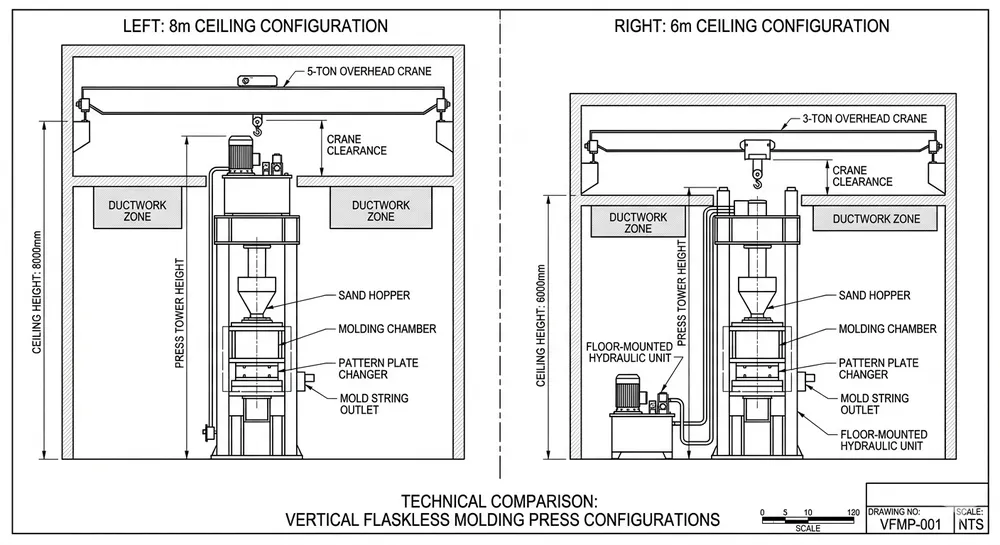
- Standard line design assumes 8 meters minimum ceiling height. We've configured lines for 6-meter ceilings (a European buyer needed this in 2019), but it requires a modified sand hopper and a different conveyor routing. If your ceiling is under 8 meters, flag this before ordering — it changes the equipment configuration.
- You also need overhead crane access for assembly. Minimum 10-ton crane capacity at the installation area, with enough hook height to lift the molding press frame upright.
Utility connections:
| Utility | Specification |
|---|---|
| Electrical supply | 380V / 3-phase / 50Hz (or 480V/60Hz for North American sites) — 150 kVA minimum |
| Compressed air | 6–8 bar, 3 m³/min continuous supply |
| Water (if sand cooling used) | 2 m³/hour, ambient temperature |
Red flag: Insufficient floor loading is the single most common facility prep failure we encounter. A 15-ton molding press cycling under full hydraulic pressure on an undersized slab produces progressive micro-cracking in the concrete. You won't see it for months. By the time the tolerance starts drifting, you're looking at a full foundation replacement with the line dismounted. Get a structural engineer to sign off on the pad before you pour.

Container unloading and modular frame assembly
We design every line to ship in standard 40HQ containers (12.03m × 2.35m × 2.69m internal dimensions). A complete automatic flaskless clay sand processing line typically fills 2–3 containers depending on capacity and options. Each structural section is match-marked at the factory with stamped alignment codes, so your installation crew doesn't have to figure out what connects where.
Unloading sequence:
- Structural frames first — these are the heaviest modules (the molding press frame alone is typically 4–6 tons). Unload with an overhead crane or a heavy forklift rated for the weight. Each frame sits on shipping skids with lifting points clearly marked.
- Hydraulic power unit — ships on its own skid, crated separately. Keep it upright during unloading. The reservoir is drained for shipping but the internal plumbing is pre-connected.
- Control cabinets — last off, first to store in a dry area. These are the most sensitive to moisture and impact. Do not stage them outdoors.
Frame assembly procedure:
- Lay out all frame sections in assembly order using the match marks. Each section is stamped with a letter-number code (A1, A2, B1, etc.) that corresponds to the assembly drawing.
- Set frame sections onto the foundation anchor bolts. Do not torque the anchors yet — leave them finger-tight until all sections are aligned.
- Use a laser level to verify vertical and horizontal alignment across the full line length. Acceptable deviation: ±1mm over any 3-meter span.
- Once alignment is confirmed, torque anchor bolts to spec (typically 350–400 Nm for M24 Grade 8.8 bolts, but confirm against the assembly drawing for your specific configuration).
Red flag: Do not remove the yellow shipping braces until frame sections are bolted to the foundation and aligned. Those braces hold critical alignment from the factory through ocean transit. I've seen crews strip them off during unloading to "make handling easier" — and then spend two days re-aligning sections that were perfect when they left Qingdao.
Hydraulic system installation and pressure testing
The hydraulic system is what makes a flaskless line hold ±0.5mm mold tolerance at production speed. A loose fitting or a misaligned cylinder here doesn't just leak — it degrades every mold the line produces until someone catches it.
Power unit connection:
- Mount the hydraulic power unit on its designated pad (marked on the foundation layout). The unit should sit level within ±0.5mm. Shim as needed.
- Route hydraulic lines from the power unit to the molding press cylinders, squeeze cylinders, and pattern draw mechanisms. We ship the hose assemblies pre-made to length with labeled connectors — match the tags to the schematic.
- Fill the reservoir with ISO VG 46 hydraulic fluid to the marked level. Run the power unit at low pressure for 15 minutes to circulate fluid and purge air from the lines. (We always ship a small bottle of the exact fluid we used for factory testing — match the spec if you're sourcing locally.)
Pressure testing protocol:
This is the step that would have prevented the scenario at the top of this article. Do not skip it.
- Close all circuit valves. Bring system pressure to 75 bar and hold for 10 minutes. Inspect every fitting visually.
- Increase to 150 bar (rated operating pressure). Hold for 15 minutes. Acceptable pressure drop: ≤2 bar over 15 minutes.
- Increase to 225 bar (1.5× rated capacity). Hold for 10 minutes. This is the proof test. If a fitting is going to fail, it fails here, not at 3 AM during a production run.
- Bleed pressure back to zero. Re-inspect all fittings and cylinder seals.
Cylinder alignment check:
With the system at zero pressure, manually cycle each hydraulic cylinder through its full stroke using the manual override on the directional valve. Watch the rod for lateral movement. Any visible side-loading means the cylinder mount is misaligned — loosen, re-shim, re-check. This takes 30 minutes and prevents the exact seal failure mode that kills production uptime.
Red flag: Factory bench testing does not eliminate the need for field pressure testing. Components that passed at our facility have been through container stacking, ocean vibration, and port handling. Fittings that were tight in Qingdao can be finger-loose by the time they reach your floor.
Electrical wiring and PLC integration with existing foundry controls
Clay sand processing line PLC integration is where most installation teams slow down — not because it's complex, but because the wiring sequence matters and skipping steps creates problems that look random once the line is running.
Control cabinet installation:
- Mount the main control cabinet on the wall or freestanding frame location shown on the layout drawing. Distance from the molding press should not exceed the cable lengths we supply (typically 15–20 meters for sensor runs).
- Grounding: Run a dedicated ground bus from the cabinet to a ground rod driven at least 2 meters deep. Ground impedance should measure ≤4 ohms. Connect the cabinet ground, all sensor shields, and the HMI enclosure to this bus.
Red flag on grounding: Incorrect or high-impedance grounding is the single hardest commissioning problem to troubleshoot after the fact. It causes phantom sensor readings — proximity sensors triggering when nothing is there, pressure transducers giving erratic values. The symptoms look like sensor failure, but replacing sensors doesn't fix it. We spent three days on a video call with a Southeast Asian buyer debugging this before discovering their ground rod was driven into dry sandy soil with 22 ohms impedance. Drive the rod into moist, clay-heavy soil or add a ground enhancement compound.
PLC platform:
We ship with either Siemens S7-1200/1500 or Mitsubishi Q-series, buyer's choice. The selection depends on what your maintenance team already knows and what's available from local suppliers for replacement parts. If you're in Europe or the Middle East, Siemens parts are easier to source. Southeast Asia tends to stock Mitsubishi. We load the program at the factory and ship a backup on USB.
HMI configuration:
The touchscreen HMI ships pre-loaded with your selected language — English, Spanish, or Arabic. (We added Russian last year after three consecutive orders from Central Asian buyers.) Unit settings (metric vs. imperial, bar vs. PSI) are configurable from the settings screen. Your operators don't need to touch the PLC program for day-to-day adjustments — cycle time, compaction pressure, squeeze dwell time are all adjustable from the HMI.
Sensor network verification:
Before powering the PLC, verify every sensor individually:
- Proximity sensors (mold position, pattern plate detection): trigger each one manually and confirm the corresponding PLC input LED lights. If it doesn't, check the cable connection and the sensor gap — 2–5mm is typical for the inductive sensors we use.
- Pressure transducers (hydraulic circuits): with system at zero pressure, confirm 4 mA output. At rated pressure, confirm 20 mA output. A sensor reading 4.2 mA at zero is acceptable. A sensor reading 6 mA at zero is drifting and should be replaced before commissioning.
- Temperature sensors (sand moisture, hydraulic oil): compare readout against a reference thermometer. Acceptable deviation: ±2°C.
Integration with existing foundry controls:
If the flaskless line needs to talk to your existing sand reclamation system, pouring line, or cooling conveyor, the communication protocol matters. We support Modbus RTU/TCP and Profinet. Modbus is simpler to wire and debug — if you don't have a specific reason to use Profinet, start with Modbus. We provide the register map so your controls integrator can map our outputs to your existing system's inputs.
Remote diagnostics module:
The 4G cellular module mounts inside the control cabinet. Once connected to your local cellular network, it gives our engineers in Qingdao real-time access to PLC error logs, sensor status, and parameter adjustments. This is how we support commissioning remotely — your team handles the physical work on the floor, and we watch the control data in real time.

Sand system hookup — preparation, delivery, and reclamation circuits
The high-volume flaskless molding system can only produce at its rated speed if the sand system keeps up. A molding line rated at 200 molds/hour consumes sand at a pace that exposes any bottleneck in the preparation, delivery, or reclamation circuit within the first shift.
Sand preparation circuit:
Connect the sand mixer output to the molding line's sand hopper via the overhead belt conveyor. The mixer needs to deliver prepared sand at a rate that keeps the hopper above 30% capacity continuously. If the hopper drops below 30%, the PLC will pause the molding cycle — this is a built-in protection against dry molds, but it also means any sand delivery interruption directly cuts your output rate.
Calibrate the moisture control sensor before first production. Target moisture content for clay-bonded sand is typically 3.0–3.8% depending on your clay type and binder ratio. The sensor is a capacitance-type probe mounted in the mixer discharge chute. Calibrate it against three lab-dried samples at known moisture levels. This takes about an hour and prevents the most common first-week quality issue: inconsistent compaction due to moisture drift.
Sand delivery circuit:
- Belt conveyor from mixer to hopper: verify speed matches consumption rate. At 200 molds/hour with a typical mold sand volume, you need roughly 8–12 tons/hour of prepared sand delivered continuously.
- Hopper level sensor: confirm the PLC receives the high/low level signals correctly. These signals control the mixer start/stop cycle.
Reclamation circuit:
Connect the shakeout sand return path to your reclamation equipment — typically a magnetic separator, then a screening unit, then back to the preparation mixer. The reclamation circuit needs to recover ≥95% of the sand for the economics to work at this production rate. If the reclamation system can't keep up with 200 molds/hour of spent sand, you're buying virgin sand within days. Size the reclamation capacity to at least 110% of the molding line's consumption rate to maintain a buffer.
(We've had buyers install the molding line first and plan to "add reclamation later." Within two weeks they're spending more on new sand than the reclamation equipment would have cost. Connect the full Clay Sand Processing Line circuit from day one.)
Commissioning sequence and production validation
Pre-commissioning checks first. Do not start the commissioning sequence until every item on this list reads "verified":
| System | Check | Status |
|---|---|---|
| Hydraulic | Pressure test passed at 225 bar, all fittings re-torqued | ☐ |
| Hydraulic | Cylinder alignment verified, no side-loading | ☐ |
| Electrical | Ground impedance ≤4 ohms | ☐ |
| PLC | Program loaded, backup USB on-site | ☐ |
| Sensors | All proximity, pressure, and temperature sensors reading correctly | ☐ |
| HMI | Language, units, and parameter limits configured | ☐ |
| Sand system | Mixer-to-hopper delivery rate confirmed | ☐ |
| Sand system | Reclamation circuit connected and flow-tested | ☐ |
| Safety | All emergency stops tested (every station) | ☐ |
| Safety | Light curtains and interlocks functional | ☐ |
| Remote | 4G diagnostics module connected, Qingdao team can see live data | ☐ |

Commissioning sequence:
- Dry cycle (no sand): Run the molding press through 50 complete cycles without sand. Watch for smooth hydraulic movement, correct pattern plate indexing, proper squeeze stroke travel. Listen for any abnormal hydraulic noise (cavitation sounds like gravel in a pipe). Measure cycle time — it should match the factory test report within ±0.5 seconds.
- Wet cycle (sand, no pour): Load sand into the system and run 100 cycles. Inspect the first 10 molds manually for compaction uniformity, surface definition, and parting line accuracy. Measure mold dimensions against the pattern at 5 points. Target: ±0.5mm on all dimensions.
- Production validation run: Run the line for 4 continuous hours at target production speed. Log mold count per hour, cycle time per mold, and dimensional checks every 50 molds. You're looking for stability: consistent cycle time, consistent dimensions, no progressive drift.
Your target outputs for a standard automatic clay sand line commissioning:
| Parameter | Target | Acceptable Range |
|---|---|---|
| Mold output | 200 molds/hour | 190–210 molds/hour |
| Dimensional tolerance | ±0.5mm | ±0.7mm max during break-in |
| Cycle time stability | ≤±0.3 sec variation | ≤±0.5 sec first 500 molds |
| Hydraulic pressure stability | 150 bar ±3 bar | 150 bar ±5 bar |
Every line we ship includes a factory commissioning report — the test data from your specific unit's trial run at our facility. Use this as your baseline. If your field measurements differ from the factory report by more than 10% on any parameter, something in the installation needs attention before you pour metal.
Red flag: Do not run production castings until you've completed the full 4-hour validation run. Early casting defects from an un-tuned line are extremely expensive to diagnose because the root cause could be hydraulic, electrical, sand preparation, or mechanical — and the defective castings don't tell you which one. Validate the line mechanically first. Then pour.
For detailed rated specifications to benchmark your commissioning results, see the automatic flaskless line specifications.
Remote commissioning — how video-guided installation works across 14 countries
Not every buyer can fly a Chinese engineer to site for commissioning. We designed the remote support process to work without it.
Here's how it runs: one of our process engineers joins your installation team on a live video call — typically through WeChat, WhatsApp, or Teams, whatever works at your location. Your team does the physical work: connecting hoses, torquing bolts, running cable. Our engineer watches via camera, reads the PLC data through the 4G remote module, and calls out each step.
What your team needs:
- At least two technicians who can read hydraulic schematics and electrical wiring diagrams
- A multimeter and basic hydraulic tooling (torque wrench, pressure gauge, fitting wrenches)
- Overhead crane access for frame assembly
- Stable internet for video calling and remote PLC access
We've commissioned lines this way in Turkey, Mexico, Indonesia, Saudi Arabia, Egypt, Nigeria, Poland, and eight other countries. It works well when your team has mechanical and electrical competence — they don't need experience with this specific equipment, because we provide the experience remotely.
When doesn't it work? If your installation crew can't identify a solenoid valve from a sight photo or doesn't own a multimeter, remote commissioning will be frustrating for everyone. In those cases, we send an engineer on-site. We'll tell you honestly which scenario fits your situation.
First-year spare parts kit:
Every line ships with a consumable kit covering the first 12 months of operation: hydraulic seals (full set for all cylinders), proximity sensors (2 spares per station), solenoid valves (1 per circuit), and PLC I/O modules (1 spare of each type). This kit means your maintenance team doesn't wait 6 weeks for sea freight when a $30 proximity sensor dies at 2 AM. (We sized the kit based on failure rate data across our installed base — the quantities aren't arbitrary.)
If you're evaluating whether a Vertical Flaskless Clay Sand Processing Line might be a better fit for low-ceiling facilities, that's a configuration question to settle before ordering — the setup sequence is similar, but the facility requirements differ.
Setup mistakes that cost production time
These are the errors we see repeatedly across installations. Most are covered in the step-by-step sections above, but consolidating them here makes it easier for your installation lead to brief the crew before starting.
1. Misaligned hydraulic cylinders What happens: Seal failure within 48–72 hours of production under 150-bar cycling pressure. Line down for seal replacement. Prevention: The cylinder alignment check in the hydraulic section. 30 minutes.
2. Incorrect PLC parameters What happens: Cycle time too fast (incomplete compaction → soft molds), squeeze pressure too low (dimensional drift), or dwell time too short (pattern release damage). First 500 molds go to scrap before someone catches it. Prevention: Load the factory program without modification for initial commissioning. Make parameter adjustments only after validating the baseline.
3. Insufficient sand reclamation capacity What happens: Reclamation system can't process spent sand as fast as the molding line consumes it. Sand supply runs out mid-shift. You're buying truckloads of virgin sand. Prevention: Size reclamation at 110% of molding line consumption rate. Connect the full circuit before first production.
4. Skipping the dry cycle What happens: Mechanical issues (binding, misalignment, hydraulic sequencing errors) get discovered only when sand is in the system. Troubleshooting with sand in the line is slow and messy. Prevention: Run 50 dry cycles and resolve all mechanical issues before introducing sand.
5. Poor electrical grounding What happens: Phantom sensor readings cause intermittent PLC faults. Mold defects appear randomly. Sensor replacement doesn't help. The problem looks electrical but the root cause is in the ground path. Prevention: Measure ground impedance before connecting any sensors. Target ≤4 ohms. If you're on sandy or rocky soil, use a ground enhancement compound around the rod.
If you're weighing the complexity of a fully automatic line against your team's capabilities, the comparison between automatic vs semi-automatic flaskless lines covers the practical trade-offs.
FAQ
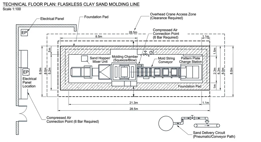
How much floor space does an automatic flaskless clay sand processing line need?
A typical line for 200 molds/hour occupies roughly 25–35 meters in length and 8–12 meters in width, depending on whether the sand reclamation circuit runs inline or parallel. Ceiling clearance needs 8 meters minimum for the standard configuration. We've built lines for 6-meter ceilings, but the hopper and conveyor routing change — specify your actual ceiling height when requesting a layout.
Can I integrate a new flaskless line with my existing foundry control system?
Yes, as long as your existing system supports Modbus RTU/TCP or Profinet. We provide the I/O register map so your controls integrator can map signals between systems. Most integrations involve connecting the flaskless line's production status outputs (cycle complete, fault, mold count) to your existing SCADA or supervisory system. If you're running an older hardwired system with no fieldbus capability, we can add relay outputs for basic status signals.
What's the typical timeline from container delivery to first production mold?
With a prepared facility and an experienced installation crew, 10–14 working days is realistic. That breaks down to roughly 2 days for unloading and frame assembly, 3 days for hydraulic and electrical installation, 2 days for sand system hookup, and 3–5 days for commissioning and validation. If the facility isn't ready (foundation not poured, utilities not run), add the prep time — that's usually the variable that stretches the schedule.
Do I need a Siemens or Mitsubishi PLC?
Pick whichever platform your maintenance staff knows and your local market stocks. Both run the same program logic for the molding line. Siemens parts are easier to source in Europe, the Middle East, and Africa. Mitsubishi has stronger distribution in Southeast Asia and parts of South America. If your team has no preference, we default to Siemens S7-1200 for standard lines and S7-1500 for larger configurations with more I/O points.
What if my team has never installed a flaskless molding line before?
That's the normal case for most of our overseas installations. Your team needs mechanical and electrical competence — reading schematics, using a torque wrench, operating a multimeter — but they don't need prior flaskless line experience. We provide the experience through remote video-guided commissioning. If the skill gap is too wide for remote support, we'll recommend sending an engineer to your site and quote that service separately.

Baocun Zhu is the Senior Clay Sand Process Engineer at TZFoundry in Qingdao. With over 14 years commissioning clay sand molding, reclamation, and preparation lines for export foundries, he turns floor-space constraints and throughput targets into working production systems. His...