Casting yield is the percentage of poured metal that becomes sellable parts. On a lost foam line running cast iron or ductile iron, yield below 85% means you're pouring metal that ends up as scrap — porosity, carbon inclusions, misruns, sand collapse. Every percentage point of yield loss translates directly to wasted alloy cost, rework labor, and delayed shipments.
Lost foam casting faces yield challenges that don't exist in green sand or shell molding. The foam pattern vaporizes during pouring, and if that decomposition isn't controlled, you get gas entrapment and carbon defects. The refractory coating is the only barrier between molten metal and loose sand — if coating permeability is wrong, metal penetrates the sand or the mold collapses. Vacuum pressure must pull decomposition gases out fast enough to prevent porosity, but not so aggressively that it cracks the coating.
We've commissioned lost foam lines in 14 countries, and the yield problems always trace back to the same five variables. Control these, and your scrap rate drops. Ignore them, and you'll spend more time sorting rejects than shipping castings.
Variable 1: EPS Pattern Density and Dimensional Accuracy
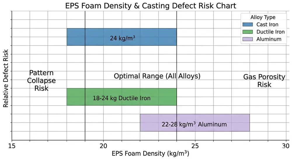
EPS foam density controls how much polymer you're vaporizing per kilogram of casting. Too low (below 18 kg/m³), and the pattern collapses during coating or sand filling. Too high (above 28 kg/m³), and decomposition gases overwhelm your vacuum system, causing porosity and carbon inclusions.
The working range for most cast iron and ductile iron applications is 18–24 kg/m³. Aluminum casting can tolerate slightly higher densities (22–28 kg/m³) because pouring temperatures are lower and decomposition is slower. We modified our coating system in 2018 to handle the full 18–28 kg/m³ range after a Middle Eastern buyer needed to run both aluminum and ductile iron on the same line.
Pattern dimensional accuracy matters because lost foam has no draft angles and minimal machining allowance. If your EPS cutting machine drifts ±0.5mm on a critical dimension, that error goes straight into the casting. CNC hot-wire cutting holds ±0.2mm, which is tight enough for most applications. Manual cutting with templates? You'll see ±1mm variation, and that shows up as inconsistent wall thickness and machining problems downstream.
Red flag: If you're seeing shrinkage porosity in heavy sections but not thin sections, check your EPS density first. High-density foam generates more gas in thick areas, and if your vacuum can't pull it out fast enough, it gets trapped as porosity.

Variable 2: Refractory Coating Thickness and Permeability
The refractory coating does two jobs: it creates a smooth casting surface, and it controls gas escape during foam decomposition. Coating thickness typically runs 0.8–1.5mm after drying. Thinner than 0.8mm, and you risk metal penetration into the sand. Thicker than 1.5mm, and the coating cracks during drying or sand compaction.
Permeability is the critical spec most buyers ignore. Coating permeability needs to match your EPS density and pouring temperature. High-permeability coatings (used for high-density foam or high-temperature alloys) let decomposition gases escape faster but sacrifice surface finish. Low-permeability coatings give you a smoother surface but trap gases if your foam density is too high.
We run permeability tests on every coating batch using a standard air-flow fixture. Target permeability for cast iron at 1400°C is 15–25 seconds per 50cc of air through a 1mm coating layer. If your coating supplier can't give you a permeability spec, you're guessing.
Coating application method affects thickness uniformity. Dip coating gives you ±0.2mm variation if your viscosity control is tight. Spray coating is faster but harder to control — we've seen ±0.5mm variation on complex geometries, and that inconsistency shows up as random surface defects.
Drying matters more than most buyers realize. Coating must dry to below 2% moisture content before sand filling, or steam generation during pouring will blow holes in your casting. We use forced-air drying tunnels with humidity monitoring — patterns exit at 1.5% moisture or they don't go to the molding station.

Variable 3: Sand Filling and Vibration Compaction
Loose sand around the coated pattern must compact uniformly to support the mold during pouring. Under-compacted sand collapses when molten metal hits it. Over-compacted sand cracks the coating before you even pour.
Vibration frequency and amplitude are the control parameters. We run 50–60 Hz frequency with 0.5–1.0mm amplitude for most cast iron work. Lower frequency (40–50 Hz) works better for large, heavy castings where you need deeper sand penetration. Higher frequency (60–70 Hz) is for small, thin-wall parts where you want surface compaction without crushing delicate features.
Vibration duration depends on flask size. A 500mm × 500mm flask needs 45–60 seconds of vibration to reach uniform compaction. Stop too early, and the top layer is loose. Run too long, and you over-compact the bottom, which can crack the coating or distort the pattern.
Sand grain size affects compaction behavior. We use 50–70 mesh silica sand for most lost foam work. Finer sand (70–100 mesh) gives better surface finish but compacts too tightly and restricts gas flow. Coarser sand (40–50 mesh) allows better gas escape but leaves a rougher casting surface.
Compaction verification: Drop a steel ball bearing from 300mm onto the compacted sand surface. It should bounce once and settle. If it bounces twice, you're under-compacted. If it doesn't bounce at all, you've over-compacted and probably cracked the coating.
Variable 4: Vacuum Pressure Control During Pouring
Vacuum pressure pulls decomposition gases out of the mold cavity as the foam vaporizes. Without vacuum, those gases get trapped as porosity. Too much vacuum, and you pull molten metal through the coating into the sand.
The working range for cast iron is -0.03 to -0.06 MPa (roughly -300 to -600 mbar). Ductile iron runs slightly higher, -0.04 to -0.07 MPa, because pouring temperatures are higher (1480–1520°C vs 1380–1420°C for gray iron) and decomposition is faster. Aluminum casting uses lower vacuum, -0.02 to -0.04 MPa, because pouring temperatures are much lower (700–750°C) and gas generation is slower.
Vacuum must stabilize before pouring starts. We program our PLC systems to hold target vacuum for 15–20 seconds before the ladle tips. If vacuum is still climbing when you pour, you'll get inconsistent gas evacuation and random porosity.
Leak detection is critical. A 2mm crack in a vacuum chamber seal can drop your effective vacuum by 30%, and you won't see it until you start getting porosity complaints. We pressure-test every vacuum chamber at 1.2× operating vacuum before commissioning, and we include leak-detection ports in the chamber design so your maintenance team can run soap-bubble tests without disassembling the system.
PLC-based vacuum control eliminates operator error. Manual vacuum valves drift, and operators adjust them based on gut feel. Our automated systems hold vacuum within ±0.005 MPa across the entire pour cycle, which is tight enough to prevent the pressure swings that cause gas entrapment.

Variable 5: Pouring Temperature and Speed
Pouring temperature affects foam decomposition rate and metal fluidity. Pour too cold, and you get misruns — the metal freezes before filling thin sections. Pour too hot, and you generate excessive decomposition gases that your vacuum can't handle, causing porosity and carbon inclusions.
For gray cast iron, the working range is 1380–1420°C. Ductile iron runs hotter, 1480–1520°C, because the spheroidal graphite structure requires higher superheat. Aluminum is much cooler, 700–750°C depending on alloy.
Pouring speed interacts with all four previous variables. Pour too fast, and the foam doesn't have time to decompose cleanly — you trap solid foam residue in the casting as carbon inclusions. Pour too slow, and the metal starts to freeze in thin sections before the mold fills.
We calculate pouring speed based on casting weight and section thickness. For a 50kg cast iron part with 8mm minimum wall thickness, target pouring time is 12–15 seconds. Thinner walls (5–6mm) need faster pouring (8–10 seconds) to prevent premature freezing. Heavier sections (15mm+) tolerate slower pouring (18–22 seconds) because thermal mass keeps the metal fluid longer.
Temperature measurement matters. Handheld pyrometers are ±15°C accurate at best, which is too loose for lost foam work. We use immersion thermocouples that read ±5°C, and we measure in the ladle immediately before pouring, not at the furnace. Metal loses 8–12°C per minute sitting in a ladle, so furnace temperature is not pouring temperature.
The interaction between pouring temperature and EPS density is where most yield problems hide. High-density foam (24–28 kg/m³) generates more gas, so you need either lower pouring temperature (to slow decomposition) or higher vacuum (to pull gases out faster). Low-density foam (18–20 kg/m³) decomposes cleanly even at higher temperatures, but the pattern is more fragile during handling.
Troubleshooting: Defect-to-Variable Map
Most lost foam defects trace back to one primary variable. This table shows where to look first.
| Defect Type | Primary Variable | Secondary Variable | Quick Check |
|---|---|---|---|
| Porosity (gas holes) | Vacuum pressure too low | EPS density too high | Increase vacuum to -0.05 MPa; verify foam density <24 kg/m³ |
| Carbon inclusions (black spots) | Pouring temperature too high | Coating permeability too low | Reduce pour temp by 20°C; switch to higher-permeability coating |
| Sand collapse (metal penetration) | Vibration compaction insufficient | Coating thickness too thin | Increase vibration time by 10 sec; verify coating >0.8mm |
| Misrun (incomplete fill) | Pouring temperature too low | Pouring speed too slow | Increase pour temp by 15°C; reduce pour time by 2–3 sec |
| Shrinkage porosity | Pouring temperature too high | EPS density too high in heavy sections | Lower pour temp; use lower-density foam in thick areas |
| Surface roughness | Coating permeability too high | Sand grain size too coarse | Switch to lower-permeability coating; use finer sand (60–70 mesh) |
This is diagnostic logic, not a guarantee. Real production involves interactions between all five variables, but the table tells you where to start when scrap rates climb.
How Automated Production Line Features Protect Yield at Scale
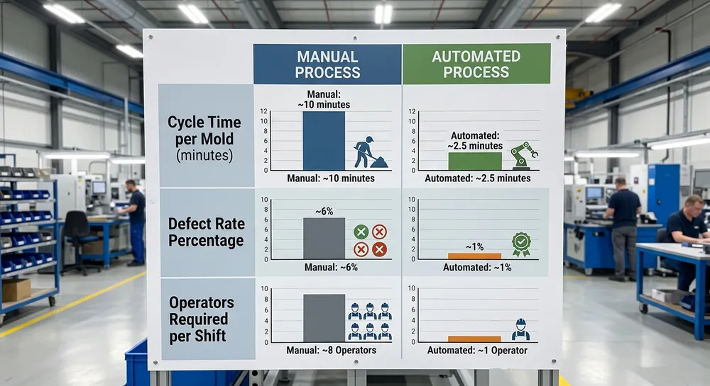
Manual lost foam lines depend on operator skill to hold these five variables in range. Automated lines enforce the ranges through PLC control, sensor feedback, and process interlocks.
PLC-based vacuum control holds pressure within ±0.005 MPa across the entire pour cycle. Manual valves drift ±0.015 MPa, which is enough to cause random porosity. Our vacuum systems use closed-loop pressure sensors that adjust valve position 10 times per second.
Programmable vibration tables store recipes for different casting types. Operator selects the part number, and the system runs the correct frequency, amplitude, and duration automatically. No guessing, no drift, no variation between shifts.
Automated coating thickness monitoring uses ultrasonic sensors to measure wet coating thickness in real time. If thickness falls below 0.8mm or exceeds 1.5mm, the system flags the pattern for re-coating before it enters the drying tunnel. Manual dip coating relies on visual inspection, which misses ±0.3mm variation.
Temperature interlocks prevent pouring if ladle temperature is outside the programmed range. Operator can't override it without supervisor code. This eliminates the "just pour it anyway" decisions that cause scrap spikes at the end of a shift.
Data logging records all five variables for every casting. When a defect shows up in final inspection, you can pull the process data for that specific mold and see exactly which variable was out of range. Manual lines have no traceability — you're guessing at root cause.
We built our first fully automated lost foam line in 2015 for a European buyer who needed 95%+ yield on ductile iron pump housings. Manual operation was giving them 82% yield with high variability between operators. After automation, yield stabilized at 94% within three months, and they haven't dropped below 92% since. The equipment cost premium paid back in eight months through scrap reduction alone.
What to Do Next
If your lost foam line is running below 90% yield, start with the troubleshooting table above. Identify your most common defect type, then measure the primary variable associated with that defect. Most yield problems come from one variable drifting out of range, not from all five being wrong simultaneously.
If you're specifying a new lost foam casting production line, ask your equipment supplier for PLC-based control on vacuum pressure and vibration compaction at minimum. Those two variables cause the most scrap when left to manual control. Vacuum casting production line configurations with automated pressure regulation cost 15–20% more than manual systems, but the yield improvement pays back in under a year for most foundries running above 200 tons annually.
For coating system upgrades, specify permeability ranges that match your EPS density and alloy type. Generic "refractory coating" without a permeability spec is a gamble. We've modified lost foam coating systems for buyers who needed to switch between aluminum and cast iron on the same line — it requires dual coating tanks with different permeability formulations, but it's cheaper than running two separate lines.
EPS foam pattern production equipment should include CNC hot-wire cutting if your castings have tolerances tighter than ±0.5mm. Manual cutting is fine for rough castings, but anything going into machining operations needs the dimensional control that only CNC provides.
Send us your current yield data, casting alloy, and target output rate. We'll recommend the specific lost foam casting equipment configuration and process controls needed to hit your yield targets. Include photos of your most common defects if you have them — that tells us which variable to prioritize. Request a quote with your specifications and we'll send back a detailed line configuration with commissioning support.

Zhang Peng leads lost foam casting systems at TZFoundry, where he has spent over 12 years engineering vacuum casting lines, coating systems, and foam pattern equipment for export foundries. He specializes in defect prevention and yield optimization across cast iron...