A foundry in Southeast Asia ran their first production batch three days after equipment installation. Vacuum pressure looked good on the gauge. Coating thickness passed visual inspection. The PLC cycled through without errors.
They scrapped 40% of the first 200 castings to porosity and carbon inclusions. The problem wasn't the equipment — it was commissioning done in the wrong sequence. The vacuum system had a slow leak at a flange joint that only showed up under sustained load. The coating station was calibrated, but nobody verified dwell time against the actual EPS density being used. The PLC parameters were factory defaults for 20 kg/m³ foam, but the patterns were 24 kg/m³.
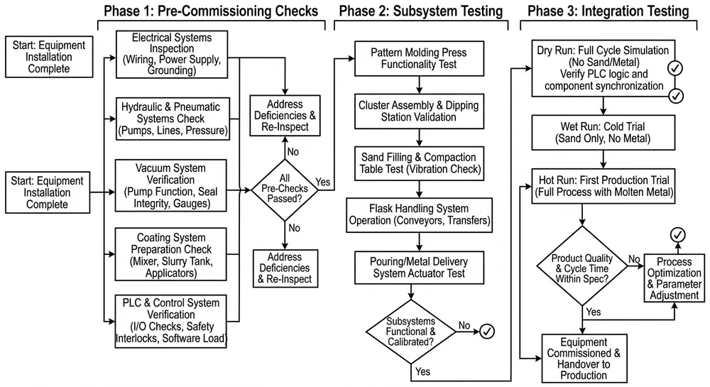
Commissioning isn't about making the machine turn on. It's about proving every subsystem can hold its spec under real production conditions before you pour metal. Skip a validation step and the defect shows up in the casting two days later when you can't trace it back to root cause.
Why Lost Foam Commissioning Failures Happen
Most commissioning problems come from three places: subsystem isolation, parameter mismatch, and no baseline documentation.
Subsystem isolation means testing the vacuum pump without testing the chamber seals, or running the coating station without confirming the foam density matches the viscosity setting. Each piece works in the factory. But when you bolt them together on-site with different ambient humidity, different power quality, and a different foam supplier, the interactions change. A vacuum system that held -0.06 MPa in Qingdao might only pull -0.055 MPa in a coastal facility with higher humidity unless you adjust desiccant capacity and check every gasket.
Parameter mismatch happens when the PLC ships with one set of cycle times and your production needs another. We program equipment for the foam density and alloy type you specify at order. But if your foam supplier changes bead grade mid-project, or you switch from gray iron to ductile iron after installation, the coating dwell time and sand fill rate need adjustment. The machine will run. The castings will have defects.
No baseline documentation means you can't tell whether a problem is new or was there from the start. Every piece of equipment we ship includes a commissioning report with the actual vacuum hold time, coating thickness range, and cycle speed measured during factory testing. That's your baseline. If vacuum pressure drops from -0.062 MPa at factory test to -0.058 MPa on-site, you know there's a leak — you're not guessing whether the system was ever capable of the spec.
Pre-Commissioning Checklist
Before you power anything on, verify these five subsystems are mechanically complete. Electrical faults are easy to troubleshoot. Mechanical assembly errors waste days.
Hydraulic subsystem:
- All hydraulic lines connected and torqued to spec (check the torque chart in the installation manual — undertorqued fittings leak, overtorqued fittings crack)
- Reservoir filled to the sight glass line with the correct ISO grade oil (we ship with ISO VG 46 unless you specified otherwise)
- Pressure relief valve set to rated pressure (typically 16 MPa for molding presses, 10 MPa for pattern handling)
- No visible leaks at pump, cylinder, or valve block
Electrical subsystem:
- Incoming power matches the nameplate (voltage, phase, frequency — a 380V three-phase machine will not run correctly on 400V without PLC parameter adjustment)
- All motor rotation directions verified (run each motor individually in jog mode and confirm the pump, conveyor, and mixer rotate the correct direction)
- Emergency stop circuit tested and functional (press every e-stop button and confirm the system drops power immediately)
- Grounding verified with a multimeter (resistance between machine frame and facility ground should be under 1 ohm)
Vacuum subsystem:
- All chamber seals in place and undamaged (check every door gasket, every port seal — a 2mm gap anywhere kills vacuum performance)
- Vacuum pump oil level correct (most rotary vane pumps fail early from running dry)
- Vacuum gauge calibrated (compare against a known-good reference gauge before you trust the reading)
- All vent valves closed during initial test
Coating subsystem:
- Coating tank filled to operating level with the correct refractory slurry (verify viscosity with a flow cup — we target 18-22 seconds Zahn #2 for standard EPS foam)
- Dip basket or spray nozzles clean and unobstructed
- Drying chamber airflow verified (measure air velocity at the inlet — should be 1.5-2.0 m/s for convection drying)
- Temperature sensors reading correctly (compare against a handheld thermometer)
PLC and HMI:
- HMI powers on and displays the home screen without errors
- All I/O modules show green status (a red light means a sensor or actuator isn't communicating)
- Recipe parameters match your production spec (foam density, alloy type, cycle time — don't assume factory defaults are correct for your process)
- Date and time set correctly (the PLC logs every event with a timestamp — wrong time makes troubleshooting impossible later)
This checklist takes two hours. Skipping it costs two days when you're hunting for a loose wire or a missing gasket after the system won't hold vacuum.

Step 1: Hydraulic System Pressure Test
Start with hydraulics because a pressure fault will damage seals and cylinders if you run it under load.
Close all hydraulic actuators (cylinders retracted, valves in neutral). Start the hydraulic pump and let pressure build to the relief valve setting. Watch the pressure gauge. It should climb smoothly to the set point (typically 16 MPa for molding presses) and hold steady. If pressure fluctuates or drops, you have a leak.
Check every fitting, every hose, every cylinder rod seal. Hydraulic leaks show up as oil mist, drips, or wet spots. External leaks are obvious. Internal leaks (across a piston seal or a valve spool) show up as slow pressure decay when the pump stops. If pressure drops more than 0.5 MPa in 10 minutes with the pump off and all actuators locked, you have an internal leak that needs repair before you cycle the machine.
Run each actuator through its full stroke in manual mode. Extend and retract every cylinder. Open and close every valve. Watch for jerky motion (air in the system), slow response (restriction in the line), or failure to reach full stroke (mechanical interference or wrong cylinder size). Cycle each actuator five times. If it works once and fails on the third cycle, you have an intermittent problem that will stop production later.
We've commissioned lines where the hydraulic system tested fine in the factory but failed on-site because the customer's facility had 35°C ambient temperature and the oil viscosity dropped below spec. The pump couldn't maintain pressure. We added an oil cooler and the problem disappeared. Hydraulic systems are sensitive to temperature — if your facility is hotter or colder than 20-25°C, expect to adjust flow rates or add cooling.
Step 2: Vacuum System Integrity Test
Vacuum performance determines whether you get dense castings or porous scrap. Test it properly.
Close all chamber doors and seal every port. Start the vacuum pump and pull the chamber down to the target pressure (typically -0.06 to -0.08 MPa for cast iron, -0.08 to -0.10 MPa for aluminum). Once you hit target pressure, close the isolation valve between the pump and the chamber. Stop the pump. Watch the vacuum gauge.
Pressure should hold steady for at least 10 minutes. If vacuum decays faster than 0.005 MPa per minute, you have a leak. The most common leak points: door gaskets (check for debris or damage), penetration seals (where sensors or actuators pass through the chamber wall), and flange joints (undertorqued bolts or damaged O-rings).
Use a soap solution or ultrasonic leak detector to find the leak. Spray every joint, every gasket, every weld seam. Bubbles or ultrasonic noise tell you where air is getting in. Fix the leak and retest. Don't move forward until the chamber holds vacuum for 10 minutes with less than 0.005 MPa decay.
We've seen buyers skip this test and run production with a slow leak. The vacuum gauge showed -0.06 MPa at the start of the cycle, but by the time metal poured, pressure had decayed to -0.04 MPa. The castings had porosity in the heavy sections where metal solidified last. They blamed the foam, the coating, the pouring temperature — everything except the vacuum system. A proper leak test on day one would have caught it.
(Note: if you're commissioning in a high-humidity environment, add a desiccant cartridge to the vacuum line. Moisture vapor loads the pump and reduces ultimate vacuum. We learned this after commissioning three lines in Southeast Asia.)
Step 3: Coating Station Calibration
Coating thickness and uniformity control carbon defects and surface finish. Calibrate before you coat your first pattern.
Fill the coating tank with refractory slurry mixed to the correct viscosity. We target 18-22 seconds Zahn #2 cup for standard EPS foam (density 18-24 kg/m³). Higher density foam needs thinner coating (16-18 seconds) because it absorbs less. Lower density foam needs thicker coating (22-25 seconds) because it's more porous.
Dip a test pattern (same size and geometry as your production parts) into the coating. Hold it submerged for the programmed dwell time (typically 10-15 seconds for dip coating, 5-8 seconds for spray coating). Remove the pattern and let excess coating drain for 30 seconds. Measure wet coating thickness with a wet film gauge at three locations: top, middle, bottom. Target thickness is 0.8-1.2 mm wet (which dries to 0.4-0.6 mm).
If coating thickness varies more than 0.2 mm between locations, adjust dwell time or slurry viscosity. Thick coating at the bottom and thin at the top means drainage time is too short. Thin coating everywhere means viscosity is too low or dwell time is too short. Thick coating everywhere means viscosity is too high.
Move the coated pattern into the drying chamber. Set air temperature to 50-60°C and airflow to 1.5-2.0 m/s. Dry until the coating is firm to the touch (typically 2-4 hours depending on coating thickness and humidity). Measure dry coating thickness with a dial gauge. It should be 0.4-0.6 mm. If it's under 0.4 mm, increase wet thickness. If it's over 0.6 mm, reduce wet thickness.
Run five test patterns through the coating cycle. Measure thickness on each one. If all five fall within 0.4-0.6 mm dry thickness with less than 0.1 mm variation, the station is calibrated. If variation exceeds 0.1 mm, check slurry mixing (refractory powder may be settling), dip basket motion (uneven immersion), or drying airflow (uneven temperature distribution).

Step 4: PLC Parameter Verification
The PLC controls cycle timing, vacuum sequencing, and sand fill rate. Wrong parameters cause defects even when the hardware is perfect.
Open the HMI recipe screen and verify every parameter matches your production spec:
- Foam density: Must match your actual EPS bead grade (if the PLC is set for 20 kg/m³ and you're running 24 kg/m³ foam, coating dwell time and vacuum hold time will be wrong)
- Alloy type: Gray iron, ductile iron, and aluminum need different vacuum hold times and sand fill rates
- Cycle time: Total time from pattern load to sand fill complete (typically 180-240 seconds for gray iron, 240-300 seconds for ductile iron)
- Vacuum hold time: How long the system maintains vacuum after sand fill (typically 60-90 seconds — longer for thick sections, shorter for thin sections)
- Sand fill rate: Controlled by valve opening and vibration frequency (too fast causes pattern distortion, too slow allows premature metal solidification)
Run the PLC through a dry cycle with no pattern in the chamber. Watch the sequence: vacuum pump starts, chamber evacuates to target pressure, hold timer counts down, sand fill valve opens, vibration starts, sand fill completes, vacuum releases, chamber vents. Every step should execute in the correct order with the correct timing.
Check the event log. The PLC records every sensor state change, every valve actuation, every alarm. If the log shows errors or unexpected sequences, troubleshoot before you load a pattern. Common issues: sensors out of calibration (vacuum gauge reads wrong), actuators not responding (valve stuck or solenoid failed), or timing conflicts (two operations trying to run simultaneously).
We program every PLC with the parameters you specified at order, but those parameters assume your foam supplier, your sand type, and your facility conditions match what you told us. If anything changed between order and installation, the parameters need adjustment. That's normal. The PLC is a tool, not a black box — adjust it to match your actual process.
Step 5: Dry Run Integration Test
Now test the full system with a coated pattern but no metal. This is where subsystem interactions show up.
Load a coated test pattern into the chamber. Close the doors. Start the cycle. Watch every step:
- Vacuum pump starts and chamber pressure drops to target (-0.06 to -0.08 MPa for cast iron)
- Vacuum holds for the programmed time (check the gauge — pressure should stay stable)
- Sand fill valve opens and sand flows into the chamber (watch through the sight glass if available)
- Vibration activates and sand compacts around the pattern (listen for consistent vibration frequency)
- Sand fill completes and vibration stops (sand level should reach the programmed height)
- Vacuum releases and chamber vents to atmosphere
- Doors open and the pattern assembly is ready for removal
Measure cycle time from door close to door open. It should match the PLC setting within ±10 seconds. If the cycle runs long, check for slow vacuum pump (worn vanes or low oil level), restricted sand flow (valve partially closed or sand bridging in the hopper), or weak vibration (motor underpowered or mounting loose).
Remove the pattern and inspect the sand mold. Sand should be uniformly compacted with no voids, no loose areas, and no pattern distortion. If you see voids near the pattern surface, vacuum pressure was too low or hold time was too short. If the pattern is crushed or distorted, sand fill rate was too fast or vibration was too aggressive.
Run three dry cycles back-to-back. If all three complete without errors and produce uniform molds, the system is ready for metal. If any cycle fails or produces inconsistent results, stop and troubleshoot. Don't pour metal until the dry run is repeatable.
Step 6: Wet Run Validation
The first metal pour is the final commissioning test. Use a simple geometry (a test bar or a small production part) and a forgiving alloy (gray iron is more tolerant than ductile iron or aluminum).
Pour the first casting and let it cool. Shake out the sand and inspect the casting:
- Surface finish: Should be smooth with no sand burn-in, no metal penetration, and no coating spalling (if the surface is rough, coating was too thin or vacuum was too low)
- Dimensional accuracy: Measure critical dimensions and compare to the pattern (lost foam typically holds ±0.5-1.0% shrinkage depending on alloy)
- Internal soundness: Cut a test section and inspect for porosity, carbon inclusions, or misruns (if you see defects, trace back to vacuum pressure, coating thickness, or pouring temperature)
If the first casting is good, pour five more and inspect each one. Consistent results across six castings mean the system is commissioned. Inconsistent results mean you have a process variable that's not under control — usually vacuum pressure decay, coating thickness variation, or sand fill inconsistency.
We've commissioned equipment where the first casting looked perfect and the third casting had porosity. The problem was a vacuum pump that overheated after 20 minutes of continuous operation and lost capacity. The first two cycles ran fine because the pump was cold. By the third cycle, the pump was hot and vacuum pressure dropped below spec. We added a cooling fan and the problem disappeared. That's why you run multiple cycles — intermittent problems don't show up in a single test.
Common Commissioning Mistakes and How to Avoid Them
Skipping the vacuum leak test: Buyers assume the chamber is sealed because it's new. Gaskets get damaged during shipping. Bolts loosen during installation. Always test vacuum hold before you run production.
Using factory default PLC parameters without verification: The PLC ships programmed for the foam density and alloy type you specified at order. If your foam supplier changed or you're running a different alloy, the parameters are wrong. Verify every recipe parameter against your actual materials.
Not documenting baseline performance: The commissioning report we ship with the equipment shows the vacuum pressure, coating thickness, and cycle time measured during factory testing. That's your baseline. If performance degrades later, you can compare against the baseline and know whether the problem is new or was there from the start.
Running production before the dry run is repeatable: One successful dry cycle doesn't prove the system is stable. Run three cycles back-to-back. If all three produce consistent results, the system is ready. If results vary, you have a process variable that's not under control.
Ignoring ambient conditions: Humidity affects coating drying time and vacuum pump performance. Temperature affects hydraulic oil viscosity and PLC sensor calibration. If your facility conditions are significantly different from the factory test environment (20-25°C, 40-60% RH), expect to adjust parameters.
Remote Commissioning Support
We've commissioned lost foam lines in 14 countries via video call. It works when your installation team can follow instructions, read hydraulic schematics, and use a multimeter.
The process: your team connects hydraulic lines, wires control panels, and fills the coating tank following the installation manual. We join via video call and walk through the pre-commissioning checklist together. Your team performs each test while we watch and verify results. If we see a problem (vacuum leak, hydraulic pressure drop, PLC error), we diagnose it in real time and guide the fix.
Remote commissioning takes 2-3 days instead of 1 day for on-site commissioning, but it eliminates the cost and lead time of flying an engineer to your facility. It works best when you have a local technician who understands foundry equipment and can troubleshoot basic mechanical and electrical issues.
We provide the commissioning report, the PLC parameter file, and a video recording of the commissioning session. If you need to retrain operators or troubleshoot a problem later, you have the documentation.
What to Do Before You Call for Commissioning
Send us three pieces of information before we schedule commissioning (on-site or remote):
- Actual foam density and supplier: If your foam supplier or bead grade changed after you placed the order, we need to adjust coating viscosity and PLC dwell time before commissioning starts.
- Facility ambient conditions: Temperature and humidity in your production area. If you're outside the 20-25°C / 40-60% RH range, we'll adjust drying time and vacuum pump cooling.
- Alloy composition and pouring temperature: If you're running a different alloy than you specified at order, we need to adjust vacuum hold time and sand fill rate.
This information lets us prepare the correct PLC parameters and commissioning checklist before we start. It saves a day of troubleshooting on-site.
For lost foam casting equipment built to prevent first-run defects, see our lost foam casting production line page. If you're evaluating suppliers and need help specifying commissioning support, our RFQ page walks you through the technical details we need to provide an accurate quote and commissioning plan.

Zhang Peng leads lost foam casting systems at TZFoundry, where he has spent over 12 years engineering vacuum casting lines, coating systems, and foam pattern equipment for export foundries. He specializes in defect prevention and yield optimization across cast iron...