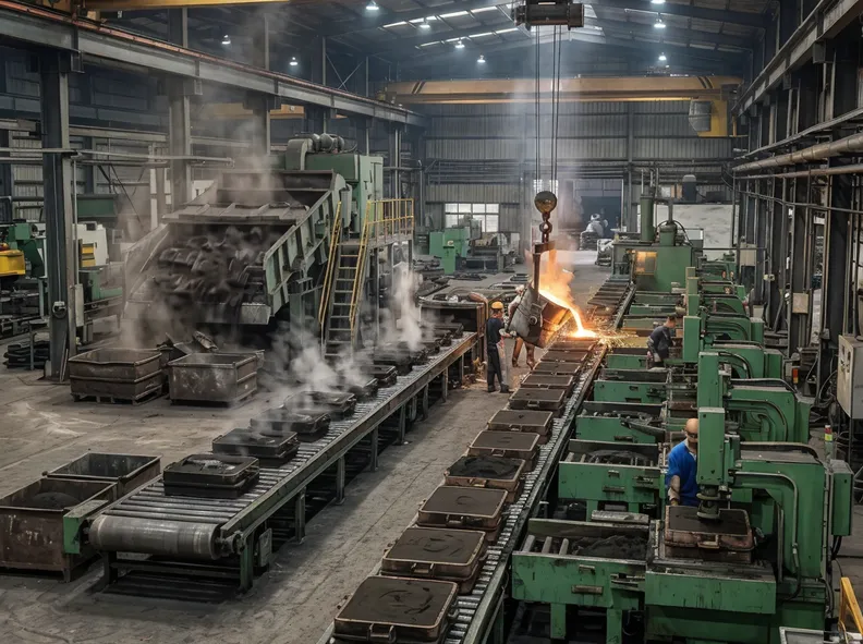
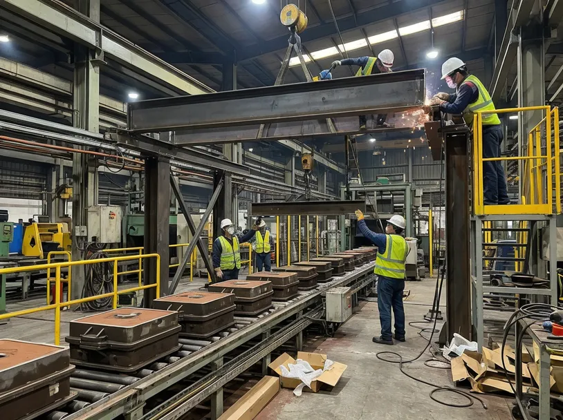
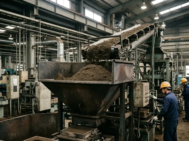
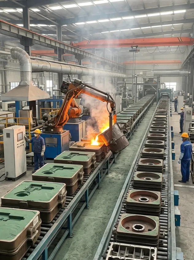
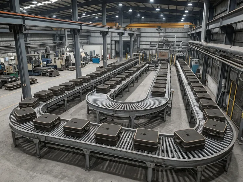
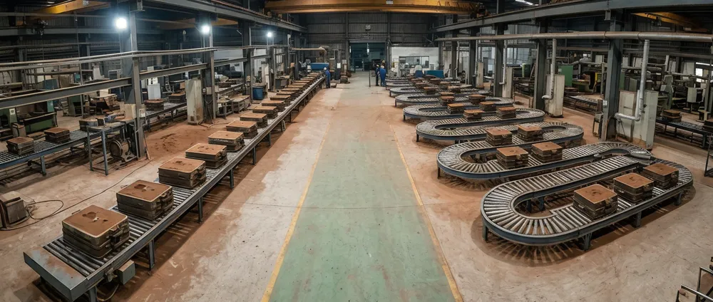
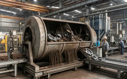
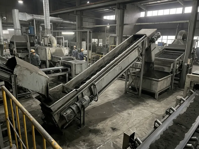
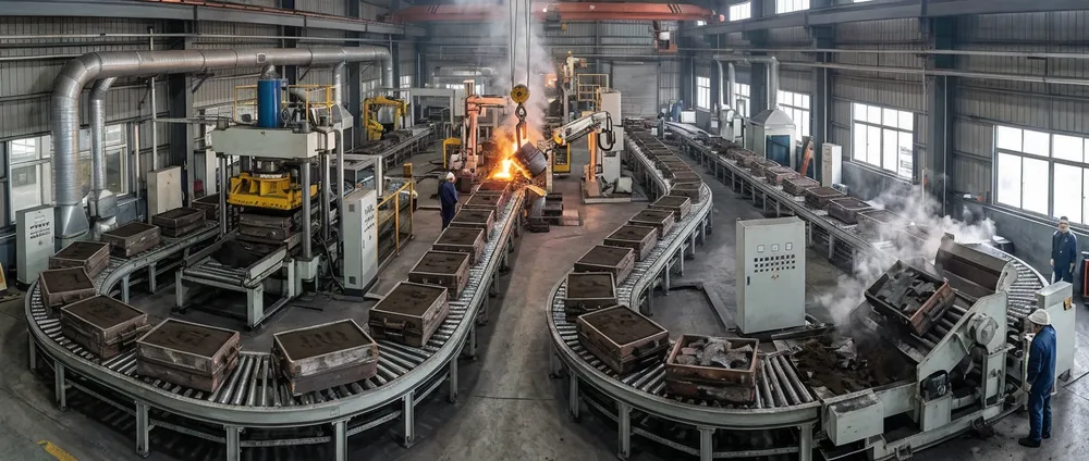
Clay Sand Processing Line
Complete clay sand molding and reclamation systems
- Clay Sand Reclamation Line
- Clay Sand Washing Line
- Flaskless Clay Sand Processing Line
- Automatic Flaskless Clay Sand Processing Line
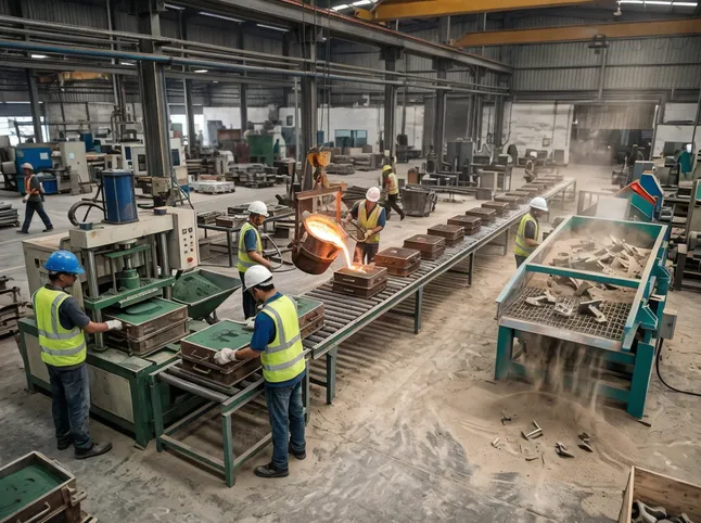
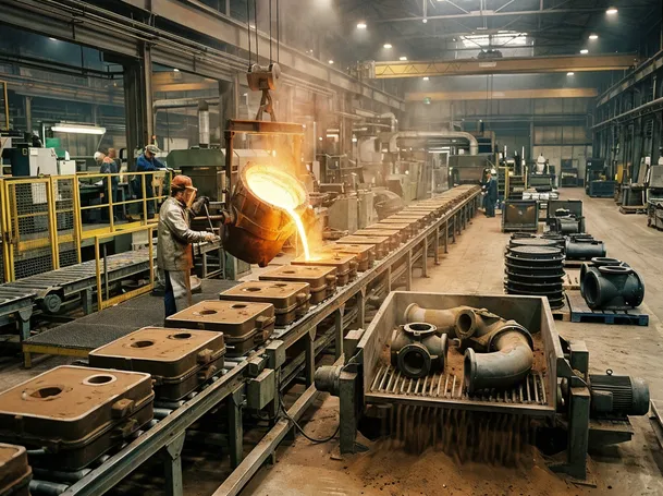
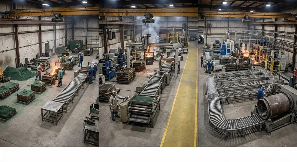
Lost Foam Casting Production Line
Advanced lost foam and investment casting solutions
- Investment Casting Machine
- Lost Foam Casting Foam Coating
- Die Casting Production Line
- Vacuum Casting Production Line
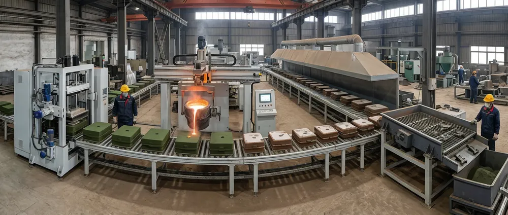
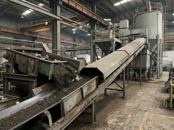
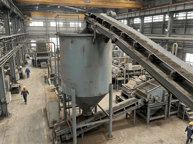
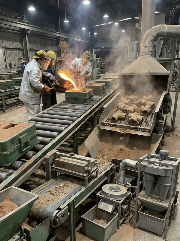
Resin Sand Production Line
High-precision resin sand molding and coating systems
- Sodium Silicate Sand Production Line
- Foundry Sand Reclamation Production Line
- Coated Sand Casting Production Line
- Resin Sand Mixer
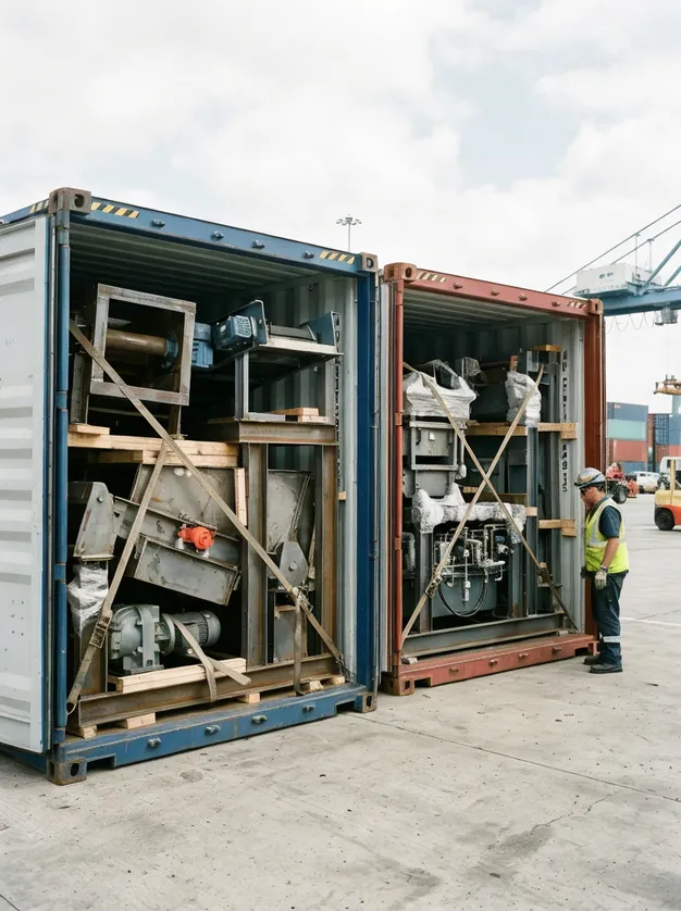
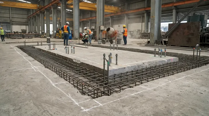
Need Custom Solutions?
Our engineering team can design equipment tailored to your foundry requirements.
Contact Engineering Team