Porosity in cast iron lost foam castings costs you more than scrap. A batch of ductile iron valve bodies with subsurface porosity makes it through visual inspection, gets machined, then fails leak testing at your customer's facility. Now you're paying for rework, expedited shipping, and the next order goes to a competitor. The root cause traces back two steps: coating thickness was wrong for the EPS density and the iron grade.
We've run defect analysis on lost foam lines across 14 installations. Porosity accounts for 60-70% of rejection in cast iron applications, and coating permeability is the variable that matters most. Get the coating thickness right for your foam density and alloy, and your porosity rate drops below 2%. Get it wrong, and you're running 15-20% scrap with no clear fix.
Why Coating Thickness Controls Porosity in Cast Iron Lost Foam
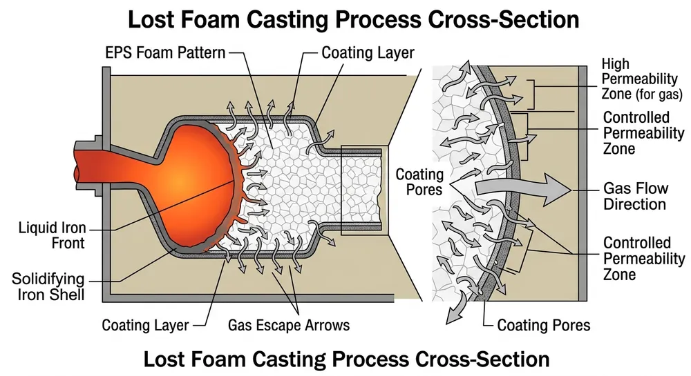
Lost foam casting burns the EPS pattern inside the mold. That decomposition releases styrene vapor and carbon residue — roughly 40 liters of gas per kilogram of foam. The coating layer on the pattern surface has one job: let gas escape fast enough that it doesn't get trapped in the solidifying iron.
If the coating is too thin or too permeable, liquid iron penetrates the coating before the foam fully decomposes. You get carbon pickup, rough surfaces, and metal-mold reactions. If the coating is too thick or too dense, gas can't escape. It gets trapped as the iron solidifies, forming subsurface porosity that shows up during machining or pressure testing.
Cast iron makes this worse than aluminum. Gray iron and ductile iron pour at 1380-1450°C, about 400°C hotter than aluminum alloys. Higher pouring temperature means faster foam decomposition and higher gas generation rate. The coating has less time to vent the gas before the iron starts to freeze.

The Coating Thickness-Permeability Balance for Cast Iron
Coating thickness and permeability work together. A 1.5mm coating with high permeability (permeability number 80-100) can vent gas as effectively as a 1.0mm coating with medium permeability (permeability number 50-70). But the thicker coating gives you better surface finish and dimensional accuracy.
For cast iron lost foam, we target these ranges:
Gray Iron (GG20, GG25, GG30)
- Coating thickness: 0.8-1.2mm
- Permeability number: 60-80
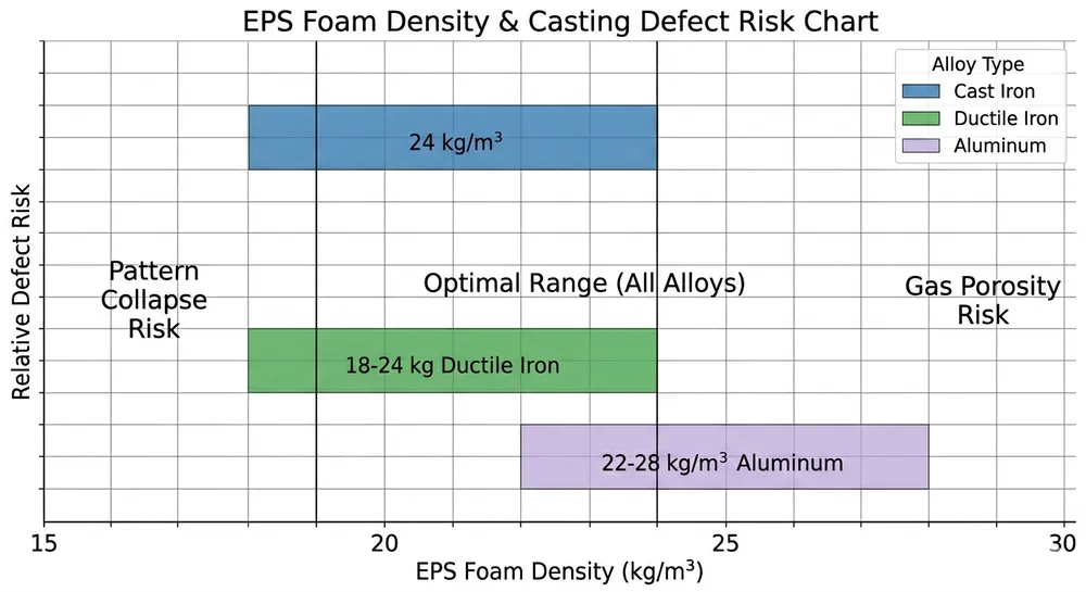
- EPS density: 20-24 kg/m³
- Drying time: 6-8 hours at 60°C
Ductile Iron (GGG40, GGG50, GGG60)
- Coating thickness: 1.0-1.5mm
- Permeability number: 70-90
- EPS density: 22-26 kg/m³
- Drying time: 8-10 hours at 60°C
Ductile iron needs thicker coating because the spheroidal graphite structure makes the iron more fluid during solidification. Thinner coating risks metal penetration. Higher permeability compensates for the extra thickness so gas can still escape.
EPS density matters because denser foam generates more gas per unit volume. If you're running 26 kg/m³ foam instead of 20 kg/m³, you need either higher permeability or longer drying time to maintain the same gas escape rate.
Step-by-Step Coating Application Protocol
This is the sequence we use when commissioning lost foam casting production lines for cast iron applications. It's designed to hit the target thickness range consistently across a production shift.
1. Verify foam pattern density and surface condition
Weigh a sample pattern and calculate density. If your patterns are supposed to be 22 kg/m³ but you're measuring 25 kg/m³, adjust your coating parameters before you start. Check pattern surface for bead fusion quality — poorly fused beads create surface irregularities that cause uneven coating thickness.
2. Mix coating to working viscosity
Target viscosity: 18-22 seconds (Ford cup #4) for dip coating, 25-30 seconds for flow coating. We use a Brookfield viscometer on production lines, but a Ford cup works for batch operations. Add water slowly — coating viscosity drops fast, and you can't reverse it without adding more powder.
3. Apply coating in controlled passes
Dip coating: 2-3 dips with 30-60 second drain time between passes. First dip builds base layer, second and third dips bring you to target thickness. Rotate the pattern during draining to prevent pooling in recesses.
Flow coating: Single pass with controlled flow rate. Our automated coating systems run at 2-3 liters per minute for medium-sized patterns (5-15 kg). Flow coating gives more uniform thickness than dip coating but requires equipment investment.
4. Measure wet coating thickness
Use a wet film thickness gauge immediately after the final coating pass. Target wet thickness is 1.5-2.0x your target dry thickness (coating shrinks 30-40% during drying). If you're targeting 1.2mm dry, measure 1.8-2.0mm wet. Mark patterns that fall outside range for re-coating or scrapping.
5. Dry coating under controlled conditions
Drying temperature: 60-70°C for refractory-based coatings. Higher temperature causes surface cracking. Lower temperature extends drying time and risks incomplete solvent removal. Drying time depends on coating thickness and humidity — 6-10 hours for cast iron applications.
We run forced-air drying ovens with circulation fans. Still-air drying takes 2-3x longer and gives inconsistent results because the coating surface dries faster than the inner layer.
6. Verify dry coating thickness and permeability
Measure dry thickness with a coating thickness gauge (electromagnetic or ultrasonic). Check permeability on sample coated plates using a permeability tester. If your production coating reads 20% below target permeability, you've either over-dried (surface sealed) or used incorrect refractory particle size in the coating mix.

Validation: How to Confirm Your Coating Parameters Work
You can't wait until castings come out of shakeout to know if your coating is right. Run these checks during process setup and periodically during production.
Coating adhesion test: Score the dried coating with a knife in a crosshatch pattern, apply tape, and pull. If more than 10% of coating pulls off, your pattern surface prep or coating binder ratio is wrong.
Permeability verification: Cut a 50mm x 50mm sample from a coated pattern. Mount it in a permeability tester and measure airflow at standard pressure (typically 10 kPa). Compare to your target range. We keep a log of permeability readings for each coating batch — if a batch reads 15% low, we adjust viscosity or drying time before coating production patterns.
Trial casting inspection: Pour 5-10 trial castings and section them. Look for subsurface porosity within 3-5mm of the casting surface. If you see porosity concentrated near gates or heavy sections, gas isn't escaping fast enough — increase permeability or reduce coating thickness. If you see metal penetration or carbon pickup, coating is too permeable or too thin.
Ultrasonic testing catches subsurface porosity without sectioning. We use UT on ductile iron castings where porosity below 2mm depth won't show up in visual inspection but will cause failures in service.
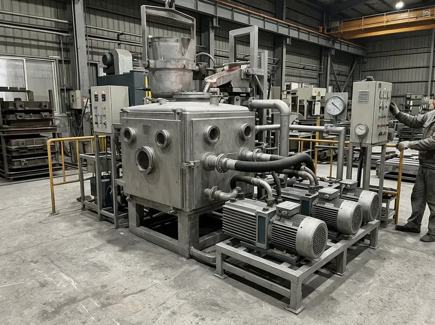
Equipment-Level Coating Control: What Your Production Line Should Handle
Manual coating works for prototype runs, but production volume requires equipment that controls the variables automatically. TZFoundry's lost foam coating systems handle EPS densities from 18-28 kg/m³ because different casting applications need different foam specs.
The coating system controls four parameters that directly affect porosity outcomes:
Viscosity control: Automated mixing with real-time viscosity monitoring. The system adds water or powder to hold viscosity within ±2 seconds of target. Manual mixing drifts 10-15% across a shift, which translates to 0.2-0.3mm thickness variation.
Application consistency: Flow coating heads with programmable flow rate and pattern rotation speed. Consistent application means consistent thickness, which means consistent permeability across your entire pattern surface.
Drying uniformity: Forced-air ovens with temperature zones and circulation control. We run three-zone drying: 50°C preheat, 65°C main drying, 55°C cooldown. This prevents surface cracking while ensuring complete solvent removal.
Thickness verification: Inline coating thickness measurement using eddy current sensors. The system flags patterns outside tolerance before they go to molding. Catching a thin-coated pattern before pouring saves you the cost of a scrapped casting plus the mold sand.
Remote diagnostics via 4G module lets you adjust coating parameters from your office. If your morning shift is running 0.1mm thick on coating, you can dial in a viscosity correction without stopping the line. (We added this feature after a Middle East customer lost half a shift troubleshooting a coating pump that was running 5% slow — now the system alerts you before thickness drifts out of spec.)
Upstream Prevention: When Porosity Problems Start Before Coating
Not all porosity comes from coating thickness. Sometimes the problem starts at foam pattern production or sand handling.
EPS bead fusion quality: Poorly fused beads create surface voids that trap gas during decomposition. The coating bridges over these voids instead of sealing them. When iron fills the mold, gas trapped in the voids can't escape and forms porosity. Check your pattern density uniformity — if density varies more than ±1 kg/m³ across the pattern, your steam cycle or cooling time needs adjustment.
Pattern storage and handling: EPS patterns absorb moisture from air. A pattern that sat in 80% humidity for three days holds 2-3% water by weight. That water turns to steam during pouring and adds to the gas load your coating has to vent. Store patterns in climate-controlled space (below 60% humidity) and coat within 48 hours of production.
Sand permeability and compaction: The sand surrounding the coated pattern provides the final gas escape path. If your sand is too fine or too compacted, gas can't escape even if the coating permeability is correct. We target sand permeability of 80-120 (AFS permeability number) for cast iron lost foam. Below 80, you're restricting gas flow. Above 120, you risk sand penetration into the coating.
Vacuum system integrity: Lost foam casting uses vacuum to pull gas through the sand and out of the mold. If your vacuum system leaks or can't maintain 0.04-0.06 MPa during pouring, gas backs up into the casting. Check vacuum level at the flask, not just at the pump — a 20% pressure drop between pump and flask means your plumbing or flask seals are leaking.

What to Do Next
If you're running above 5% porosity rejection on cast iron lost foam castings, start with coating thickness measurement. Pull 10 patterns from your current production batch and measure dry coating thickness at 5 points per pattern. If you're seeing ±0.3mm variation, your coating application process needs tightening.
For new lost foam line installations or process optimization, send us your casting specifications and current porosity rates. Our engineering team will review your EPS density, coating parameters, and vacuum system setup. We'll recommend specific equipment configurations or process adjustments based on what we've seen work across similar applications.
Most buyers in this segment start with a coating system audit — we review your current equipment, measure actual coating thickness and permeability, and provide a parameter optimization report. If equipment upgrades are needed, we'll spec the exact coating system capacity and control features for your production volume. Request a technical consultation with your casting specs and current defect rates.

Zhang Peng leads lost foam casting systems at TZFoundry, where he has spent over 12 years engineering vacuum casting lines, coating systems, and foam pattern equipment for export foundries. He specializes in defect prevention and yield optimization across cast iron...